
Iron finishing machine iron finishing roller structure

A technology for ironing rollers and ironing machines, which is used in textiles and papermaking, fabric surface trimming, etc., can solve the problems of high energy consumption, increased maintenance and use costs, and difficult to control the surface temperature of ironing rollers, and achieves uniform temperature and saves. Energy consumption, the effect of guaranteeing the quality of hot polishing

Active Publication Date: 2015-07-15
黄嘉劲
View PDF13 Cites 3 Cited by
  • Summary
  • Abstract
  • Description
  • Claims
  • Application Information

AI Technical Summary

Problems solved by technology

[0004] The above document A) because the ironing roller is directly heated by a group of electric heating tubes distributed at intervals, there is a lack of uniformity in the temperature of the roller surface, and the temperature difference is about ±10°C. The temperature difference mentioned here refers to the ironing roller. The temperature at both ends is low and the temperature in the middle is high, and the electric heating tube directly heats the ironing roller, which consumes a lot of energy
[0005] Although the above-mentioned document B) can embody the technical effect mentioned in paragraph 0009 of its specification, it has the following shortcomings: First, the overall structure is relatively complicated, for example, in addition to the complex structure of the rotary power-connecting device itself, it is necessary to install the ironing roller (the patent name A core tube is added in the roller body), and multiple groups of coils are arranged between the core tube and the ironing roller, and a heat-insulating tube is set in the core tube, and the capacitor is set in the lumen of the heat-insulating tube and will be formed by The lines drawn from the coil (patents are called the starting wire and the end wire) are connected in series with the capacitor in the heat insulation tube, so it is not only troublesome to manufacture, but also complicated to assemble; second, it is prone to failure and affects the working efficiency of the ironing roller. Because once any of the coils and / or capacitors in the multiple groups (the patent cites three groups) of coils and the plurality of capacitors (the patent cites three) is damaged, the ironing roller will not be able to show the overall heating effect, and when it is necessary When replacing the faulty coil and / or capacitor, all the coils and capacitors can only be replaced together, or even the entire heat insulation tube is replaced together, which will not only cause lengthy downtime, but also increase the cost of equipment maintenance and use; The surface temperature of the smooth roller (usually around 170-180°C) is difficult to control; Fourth, it consumes a lot of energy
[0006] The above document C) has positive significance for improving the temperature uniformity of the ironing roller, but it is not safe because the connection between the oil circuit mechanism and the ironing roller is realized through a rotary joint, and the sealing effect of the rotary joint Generally relatively fragile, once the oil leaks, it is very easy to cause a fire, so the application of the ironing roller with this structure on the ironing machine is often avoided by the industry
In addition, it can be seen from the specification and drawings of this patent that it is often difficult to meet the desired effect of uniform temperature on the surface of the ironing roller by using an electric heating tube, and the energy consumption is large
[0007] The above-mentioned document D) because of the use of gas, although it has the effect of uniform temperature on the surface of the ironing roller, it is difficult to guarantee the safety, that is, it is inconvenient to be valued by the textile printing and dyeing industry due to the high risk. In particular, the competent departments of the textile industry and technical transformation management departments Even the fire department has a tendency to prohibit the use of gas to heat the ironing roller
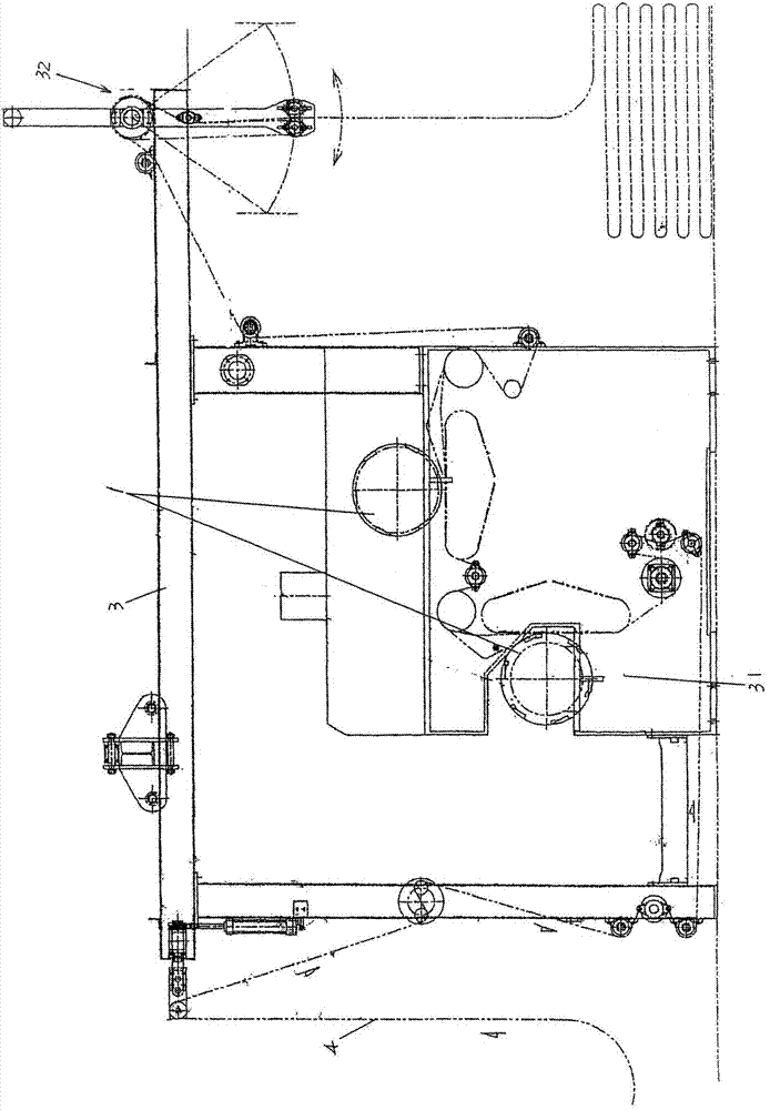
[0008] The "ironing mechanism of the ironing machine" disclosed by the Chinese utility model patent authorization announcement number CN202969046U and the "ironing device of the ironing machine" disclosed by CN202969049U both have a significant effect of improving the temperature uniformity of the surface of the ironing roller body, and can also Energy saving is realized by reusing heat energy, but the overall structure of the ironing machine tends to be complicated due to the need for a hot air circulation device, and the overall structure of the heating device installed in the roller chamber of the ironing roller is also relatively complicated

Method used


Image

  • Iron finishing machine iron finishing roller structure
  • Iron finishing machine iron finishing roller structure
  • Iron finishing machine iron finishing roller structure

Examples


Embodiment 1

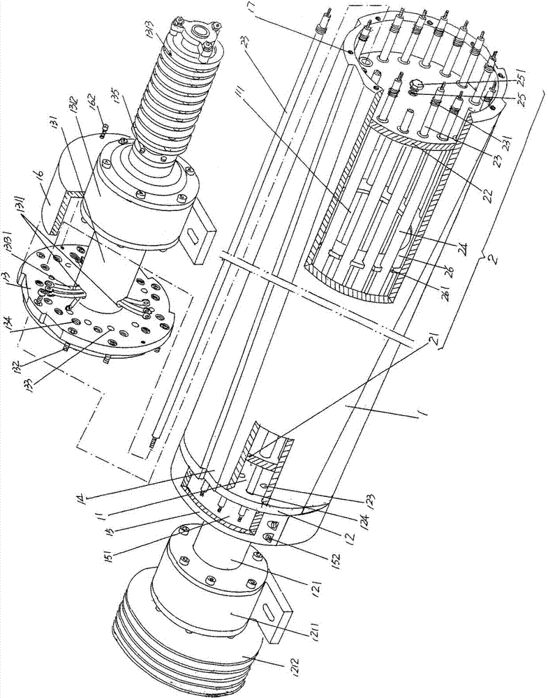
[0028] See figure 1 and figure 2 , a ironing roller body 1 preferably made of a material with good heat transfer effect such as aluminum alloy or other similar materials is given, and the length of the ironing roller body 1 is not necessarily limited in the present invention, because In the actual use process, because the width of the fabric (the industry customarily called the door width) is wide or narrow, such as 2m, 1.8m and 1.5m, etc., the length of the ironing roller body 1 can usually be determined according to the requirements of the textile printing and dyeing enterprise. Ask to be sure.

[0029] At the left end of the aforementioned ironing roller body 1 and at a position corresponding to the left cavity opening of the cavity of the ironing roller body 1, a left shaft head cover 12 is fixed, and the left shaft head cover 12 faces away from the cavity One side of 11, that is, the central position of the left side extends to form a left support shaft head 121, and the...

Embodiment 2

[0041] Only the medium introduction hole 25 is transferred to the left closure cover 21, and the rest are the same as the description of embodiment 1.

Embodiment 3

[0043] Both the left closing cover 21 and the right closing cover 22 are provided with a medium introduction hole 25, and the rest are the same as the description of Embodiment 1.


PUM


Abstract

The invention relates to an iron finishing machine iron finishing roller structure, and belongs to the technical field of textile printing and dyeing post-finishing machinery. The iron finishing machine iron finishing roller structure comprises: an iron finishing roller body, wherein a left shaft head cover is fixed on the left end, one side of the left shaft head cover forms a left supporting shaft head, a right shaft head cover is fixed on the right end, and one side of the right shaft head cover forms a right supporting shaft head; and a heating mechanism arranged in a cavity, wherein the heating mechanism comprises a left sealing disk, a right sealing disk, electric heating pipes, and an electric heating pipe protection casing, the left sealing disk and the right sealing disk are matched with the inner wall of the cavity, the group of the electric heating pipes is arranged between the left sealing disk and the right sealing disk, the left end and the left shaft head cover are fixed, the right end and the right shaft head cover are fixed, the electric heating pipe protection casing sleeves outside the electric heating pipe, a media heating chamber is formed on the cavity, a media introducing hole is arranged on the left and / or right sealing disk, and the position corresponding to the media introducing hole is provided with a media introducing hole sealing cover. The iron finishing machine iron finishing roller structure has characteristics of convenient manufacturing assembly and use maintenance, uniform iron finishing roller body temperature, assurance of fabric iron finishing quality, and energy consumption saving.

Description

technical field [0001] The invention belongs to the technical field of finishing machinery after textile printing and dyeing, and in particular relates to an ironing roller structure for an ironing machine. Background technique [0002] In the textile printing and dyeing industry, it is usually necessary to iron the fabric in the finishing process, so as to improve the surface gloss, handle and appearance of the fabric, so as to improve the quality of the fabric. The ironing roller is an important part of the ironing machine, because whether the temperature of the ironing roller is uniform or not has a direct impact on the quality of the ironing effect of the fabric. [0003] The technical information about the ironing roller can be found in the published Chinese patent documents, such as document A), the authorized announcement number CN201473762U recommends "a new type of structure ironing roller body", which is an electric heater installed in the roller shell Tube suppo...

Claims


Application Information

Patent Timeline
IPC IPC(8): D06C15/08
CPCD06C15/08
Inventor 许捷恺代勇
Owner 黄嘉劲
Learn More