Integrated type ultrahigh-pressure booster pump

A technology of ultra-high pressure and booster pumps, applied in the field of hydraulic oil pumps, can solve problems such as low working efficiency, scattered systems of devices, and increased cross-sectional size of pistons, and achieve the advantages of easy transportation and installation, saving installation space, and increasing output pressure Effect

Active Publication Date: 2015-07-15
NINGBO YINZHOU ZHONGTIAN HYDRAULIC
View PDF10 Cites 4 Cited by
  • Summary
  • Abstract
  • Description
  • Claims
  • Application Information

AI Technical Summary

Problems solved by technology

[0005] 1) For the first structure, since the principle of supercharging is to generate high pressure of a small area piston rod through the low pressure of a large area piston, if the output pressure of the pump is to be increased, the only way to increase the cross-sectional area of ​​the piston and the cross-sectional area of ​​the piston rod Therefore, either reduce the cross-sectional area of ​​the piston rod or increase the cross-sectional area of ​​the piston. However, the adjustment of this area is within a limited range after all, and to achieve ultra-high pressure output pressure, It is bound to greatly increase the cross-sectional area of ​​the piston, but this will cause a large increase in the cross-sectional size of the piston and its oil cylinder, and then make the volume of the entire booster pump larger. Therefore, on the one hand, it will increase production. cost, on the other hand it cannot be applied to applications with smaller spaces;
[0006] 2) For the second structure, because many parts are involved in the structure, such as low-pressure cylinder, booster piston, front end cover, rear end cover, integrated valve, diversion head, air guide pipe, high-pressure cylinder, one-way valve , plunger and pilot valve, the valve alone has an integrated valve, pilot valve, and the light cylinder has a low-pressure cylinder and a high-pressure cylinder. After these parts are assembled together, the structure becomes complicated; it uses an integrated valve to control the booster. The auto

Method used


Image

  • Integrated type ultrahigh-pressure booster pump
  • Integrated type ultrahigh-pressure booster pump
  • Integrated type ultrahigh-pressure booster pump

Examples


Embodiment Construction

[0027] The present invention will be described in further detail below in conjunction with the accompanying drawings and specific embodiments.

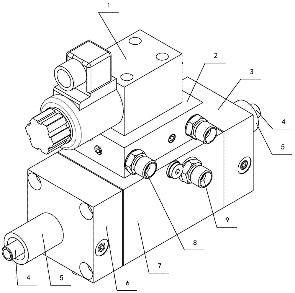
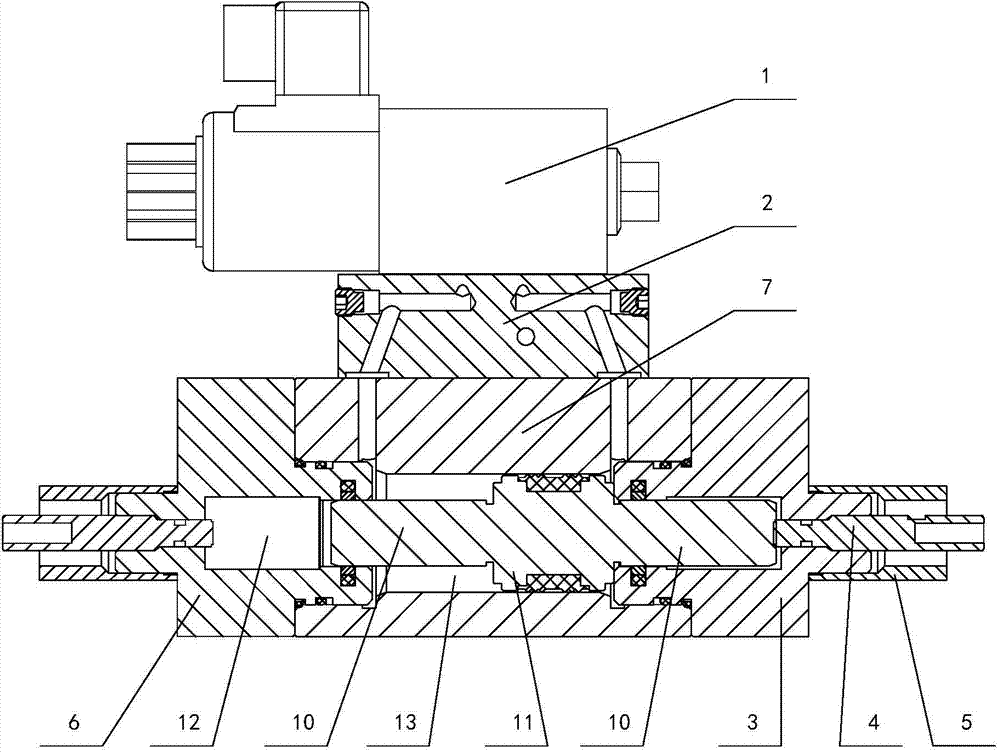
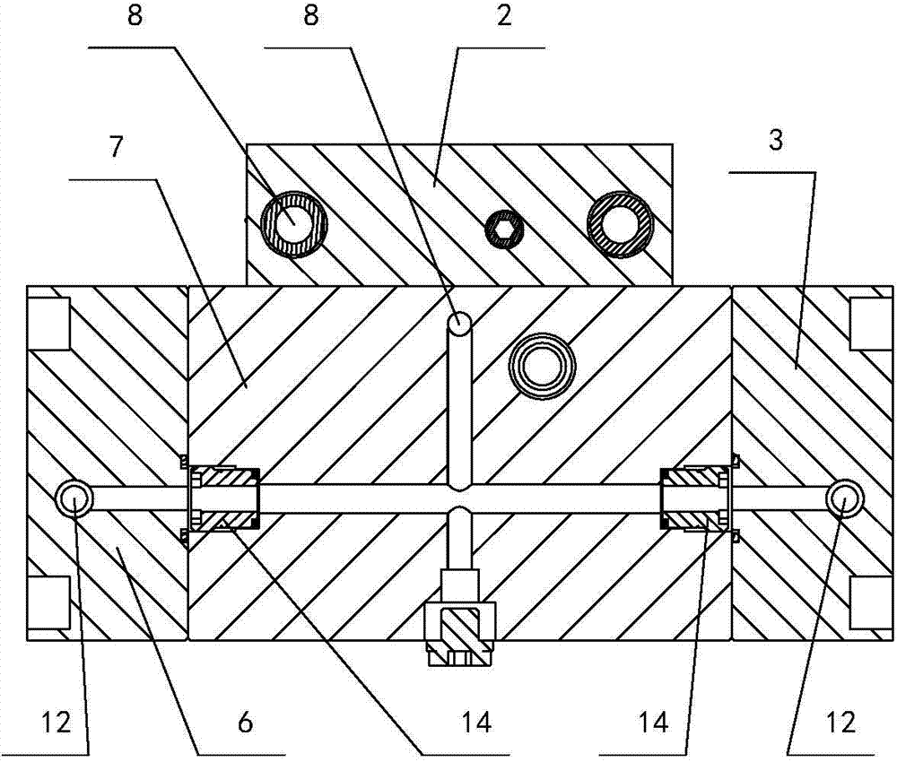
[0028] Depend on Figure 1 to Figure 5It can be seen from the schematic structural diagram and hydraulic schematic diagram of the integrated ultra-high pressure booster pump of the present invention that it includes an oil cylinder barrel 7, a left end cover 6, a right end cover 3, a piston 11 and a piston rod 10. There are two piston rods 10 and They are respectively connected to the two ends of the piston 11, the piston 11 is slidingly connected in the cylinder barrel 7, the left end cover 6 and the right end cover 3 are respectively connected to the left and right ends of the cylinder barrel 7, in other words, the left end cover 6 is connected to the oil cylinder cylinder The left end of barrel 7, the right end cover 3 is connected in the right end of cylinder barrel 7 of oil cylinder. It also includes a proportional solenoid valv...


PUM


Abstract

The invention discloses an integrated type ultrahigh-pressure booster pump which comprises a proportional electromagnetic valve, a valve plate and a proximity switch. The proximity switch can generate induction with end faces of piston rods and feed back the induction to the proportional electromagnetic valve; the valve plate is connected at the top of a cylinder barrel of an oil cylinder; the proportional electromagnetic valve is connected at the top of the valve plate; high-pressure oil cavities communicated with an oil inlet of the valve plate are formed in a left end cover and a right end cover; the oil inlet of the valve plate is communicated with an oil inlet of the proportional electromagnetic valve; two work oil cavities of the proportional electromagnetic valve are respectively communicated with low-pressure oil cavities on the two sides of a piston in a cylinder barrel of the oil cylinder; the free ends of the two piston rods are respectively in slide fit in the high-pressure oil cavity of the left end cover and the high-pressure oil cavity of the right end cover; oil outlets communicated with the two high-pressure oil cavities are formed in the cylinder barrel of the oil cylinder. By means of the structure, the pump size is smaller, the booster pump is suitable for various occasions, and the work efficiency is higher.

Description

technical field [0001] The invention relates to the technical field of hydraulic oil pumps, in particular to an integrated ultra-high pressure booster pump. Background technique [0002] At present, more and more industries need to use booster pumps to provide power to output higher pressures. Generally speaking, booster pumps with an output pressure exceeding 35MPa are usually called ultra-high pressure booster pumps in the industry. The booster pump in the prior art includes a cylinder body, a left end cover, a right end cover, a piston and a piston rod, which is equivalent to a reciprocating plunger pump, and a piston rod is respectively connected to two ends of the piston, and the left end cover and the right end cover respectively Connected to the two ends of the cylinder body, the piston is slidably connected in the cylinder body, and the ends of the piston rods at the two ends of the piston are respectively slidably connected in the left end cover and the right end co...

Claims


Application Information

Patent Timeline
IPC IPC(8): F04B9/109
Inventor 舒平国戴洪辉徐柏强孙逸成
Owner NINGBO YINZHOU ZHONGTIAN HYDRAULIC
Why Eureka
Try Eureka