
Wave beam domain time-frequency analysis method for warship line spectrum noise source positioning

A line spectrum noise, time-frequency analysis technology, applied in positioning, radio wave measurement systems, measurement devices, etc., can solve problems such as inconvenience, strict restrictions on ship motion speed, and large receiving array size, etc. The effect of improving practical operability

Active Publication Date: 2015-07-15
NORTHWESTERN POLYTECHNICAL UNIV
View PDF10 Cites 22 Cited by
  • Summary
  • Abstract
  • Description
  • Claims
  • Application Information

AI Technical Summary

Problems solved by technology

Due to the low frequency band of ship radiation noise, the size of the receiving array is required to be quite large, which will bring a lot of inconvenience in practical application
For moving targets in water, domestic scholar Shi Jie et al. (Shi Jie, Yang Desen, Shi Shengguo. Research on Robust Focusing and Localization Recognition Method of Moving Sound Source Based on Worst Performance Optimization. Acta Physica Sinica, 2011,60(6):1-11) Using the method of passive synthetic aperture, a linear array deployed on the seabed is virtualized into a large-scale planar array, so as to realize the localization of noise sources in the near field, but this method has strict restrictions on the speed of ship movement

Method used


Image

  • Wave beam domain time-frequency analysis method for warship line spectrum noise source positioning
  • Wave beam domain time-frequency analysis method for warship line spectrum noise source positioning
  • Wave beam domain time-frequency analysis method for warship line spectrum noise source positioning

Examples


Embodiment Construction

[0027] The present invention will be further described below in conjunction with the accompanying drawings and embodiments.

[0028] The technical solution adopted by the present invention to solve its technical problems is:

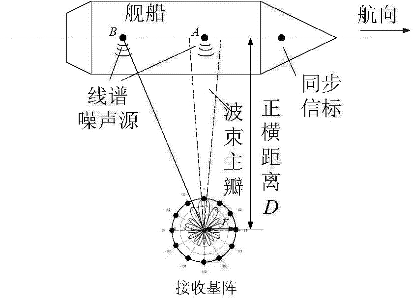
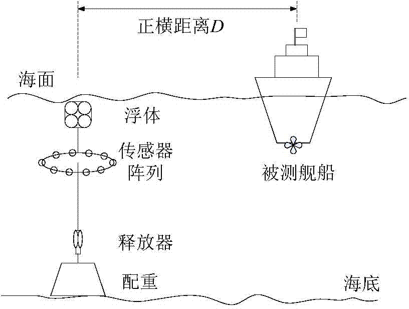
[0029] Step 1: Use a uniform circular array with the number of array elements M and radius a as the receiving base array, and fix it in the water on one side of the ship under test in a typical way of laying out submarine buoys. The ship under test moves at a constant speed along a straight line. First approach the receiving matrix, and then move away from the receiving matrix. The distance between the receiving matrix and the track of the ship under test is D. A known hydroacoustic synchrolocator is located at a fixed position on the ship as a beacon source. position, the line spectrum noise source is distributed on the ship under test along the longitudinal direction of the ship under test;

[0030] Step 2: Receive the underwater acoustic signal of ea...


PUM


Abstract

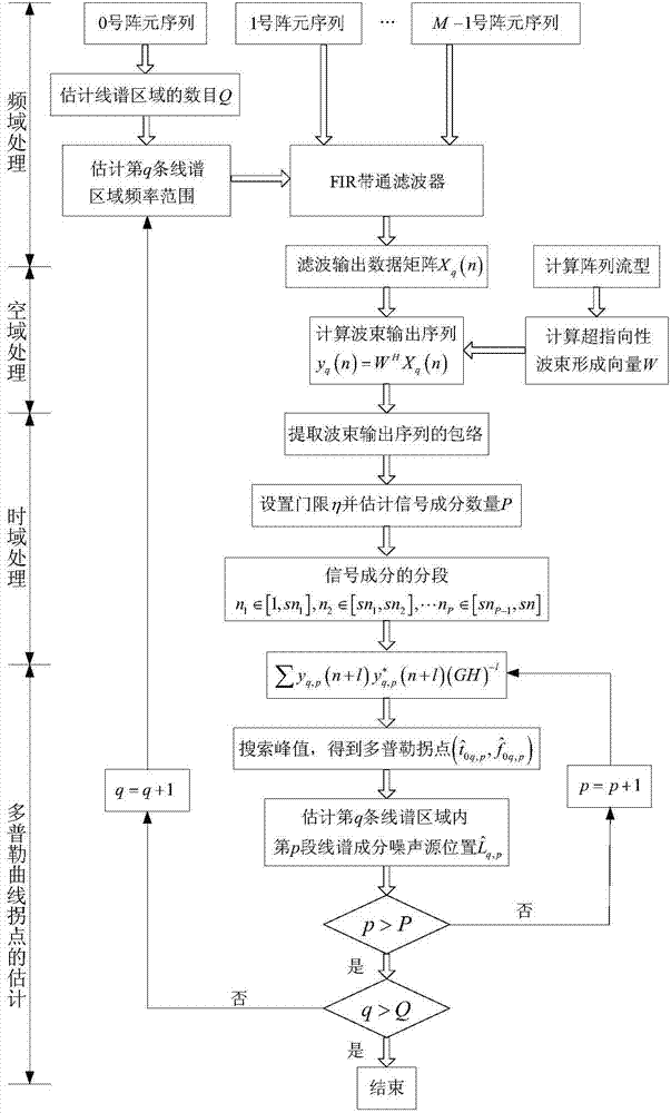
The invention provides a wave beam domain time-frequency analysis method for warship line spectrum noise source positioning. The wave beam domain time-frequency analysis method comprises the following steps: performing frequency domain filtering and super-directivity beam forming to the signals received by an array, that is, performing spatial filtering and constituent isolation on the time domain, so as to realize space-time-frequency domain combined processing of the signals; estimating the abeam moment of each line spectrum noise source, and referring to the synchronous acoustic beacon information to estimate the longitudinal position distribution of the line spectrum noise source along the warship. The wave beam domain time-frequency analysis method disclosed by the invention adopts the high-order super-directivity beam forming algorithm to greatly shrink the physical size of the receiving array and improve the actual operability of the measuring method on the premise of maintaining the receptivity; the space-time-frequency domain combined processing to the received signals is used for extracting the signal constituents of each line spectrum noise source; the time-frequency analysis method is used for obtaining the accurate time-frequency domain distribution diagram of the Doppler signals and accurately estimating the Doppler inflexions, so as to realize noise source position estimation of the high-precision multi-line spectrum and the same-frequency line spectrum.

Description

technical field [0001] The invention relates to the field of underwater acoustic measurement, in particular to estimation of ship line spectrum noise source position. Background technique [0002] The spectrum of ship radiated noise is mainly composed of the mixed spectrum formed by the superposition of continuum spectrum and line spectrum. Among them, the line spectrum noise reflects the periodic components in the noise signal, concentrated in the low frequency band below 1kHz. In the underwater radiation noise of ships, the radiation sources of different frequency bands have different radiation parts on the ship. The radiation sound of several hundred Hz is mainly excited by the mechanical vibration source, and the area where the main engine and auxiliary engine are located may be its radiation source location. The low-frequency line spectrum of tens of hertz is mainly produced by reciprocating mechanical noise, propeller blade resonance line spectrum and blade velocity ...

Claims


Application Information

Patent Timeline
Patent Type & Authority Applications(China)
IPC IPC(8): G01S5/18
CPCG01S5/22
Inventor 杨益新杨龙徐灵基
Owner NORTHWESTERN POLYTECHNICAL UNIV
Learn More