Laser scanner
A laser scanner and scanner technology, applied in the field of laser scanners, can solve the problems of high cost of mirrors, relatively high precision requirements and low efficiency, etc.
Inactive Publication Date: 2015-07-15
SUZHOU HAOCHUANG INFORMATION TECH
View PDF5 Cites 2 Cited by
- Summary
- Abstract
- Description
- Claims
- Application Information
AI Technical Summary
Problems solved by technology
These two have a common disadvantage, that is, the relative position accuracy requirements between the four devices are relatively high, and the relative position needs to be constantly debugged during production, and the efficiency is very low.
At the same time, the cost of mirrors is relatively high
Method used
View moreImage
Smart ImageViewing Examples

Examples
Embodiment Construction
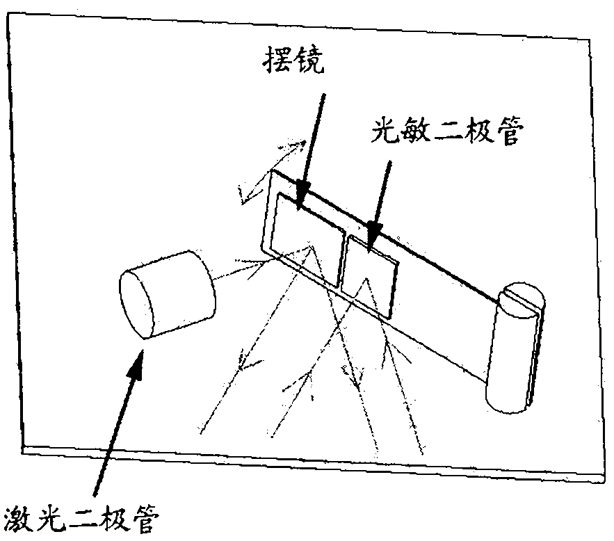
[0013] 1. Mount the swing mirror and photodiode on the flexible circuit board (FPC).
[0014] The relative position of the pendulum mirror and the photodiode can be image 3 The left and right structures shown, can also be Figure 4 The upper and lower structures shown.
[0015] 2. Fix the LED on the bracket.
[0016] 3. Fix the flexible circuit board on the bracket.
Login to View More PUM
 Abstract
The invention discloses a laser scanner. A photosensitive diode and an oscillating mirror are attached to a flexible circuit board, can be arranged at left and right positions as shown in the Fig . 3, and can also be arranged at upper and lower positions as shown in the Fig . 4. The flexible circuit board is fixed on a bracket. A laser diode is further fixed on the bracket. When the scanner works, laser emitted by the laser diode becomes linear under the oscillation of the oscillating mirror, a part of the laser reflected from an object returns to the surface of the photosensitive diode near the oscillating mirror along an original path, the intensity change of the returning light is converted into an electrical signal by the photosensitive diode, and the electrical signal is transmitted to a main board through a circuit on the flexible circuit board, and is decoded. A light path used for the scanner is simpler than a light path of the conventional scanner on the market, and a complex reflective mirror is eliminated, so that the raw material cost is low. During production, the positions of the optical devices are not required to be debugged, so that a machining process is simple and reliable. The number of reflection times is reduced, so that the light intensity attenuation of the returning light is low, and the returning light can be more easily received by the photosensitive diode.
Description
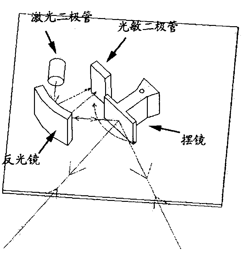
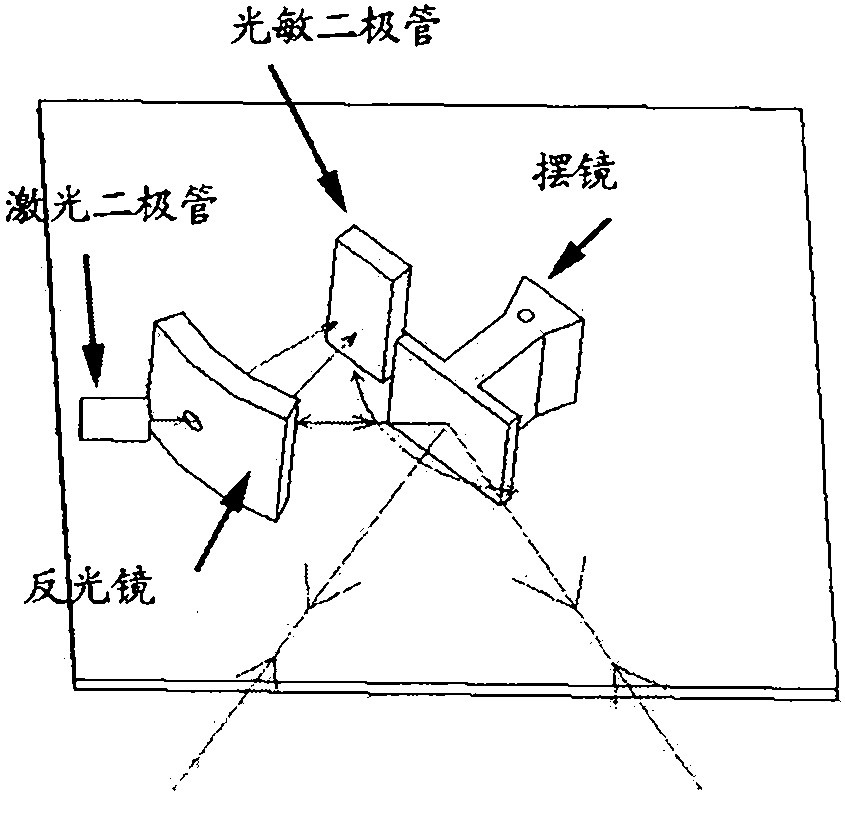
technical field [0001] A laser scanner that is used to scan barcodes, measure object sizes, etc. The present invention mainly relates to the structure of light emitting and returning light receiving of a laser scanner. Background technique [0002] There are usually two types of light-emitting and light-receiving structures used by laser scanners on the market. [0003] The first such as figure 1 , use a laser diode to emit laser light, and reflect the laser light to the swing mirror through the multi-faceted mirror, and the left and right swing of the swing mirror turns the light into a line. When the light hits the object, part of the reflected light returns to the swing mirror along the original path, and is reflected by the swing mirror to the curved reflector surface. The reflector converges the collected light onto the photosensitive diode for photosensitive. [0004] The second such as figure 2 , using a laser diode to emit laser light, the light passes through t...
Claims
Login to View More Application Information
Patent Timeline
 Patent Type & Authority Applications(China)
IPC IPC(8): G06K7/10
Inventor 周洁杨心怀王志特李丕勇杨慧
Owner SUZHOU HAOCHUANG INFORMATION TECH