Rotor and motor comprising same

A rotor and shaft technology, applied in the electromagnetic field, can solve the problem of low electrical energy use efficiency of the motor, and achieve the effects of large torque, smooth rotor, and elimination of pulsating torque

Active Publication Date: 2015-07-15
SHENZHEN TIANTIAN NEW ENERGY TECH
View PDF6 Cites 5 Cited by
  • Summary
  • Abstract
  • Description
  • Claims
  • Application Information

AI Technical Summary

Problems solved by technology

[0003] Aiming at the defect that the electric energy utilization efficiency of the motor is not high due to torque ripple in the prior art, a rotor and a motor having the rotor are provided

Method used


Image

  • Rotor and motor comprising same
  • Rotor and motor comprising same
  • Rotor and motor comprising same

Examples


Embodiment Construction

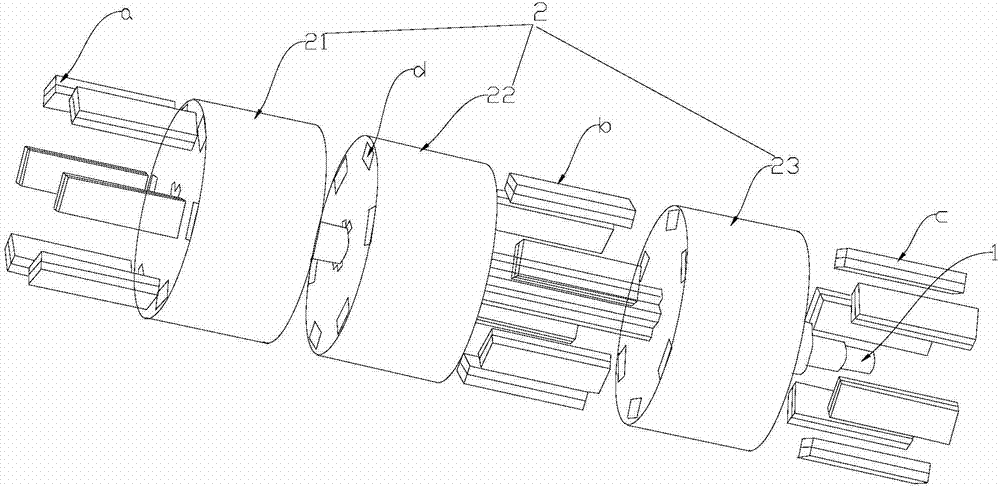
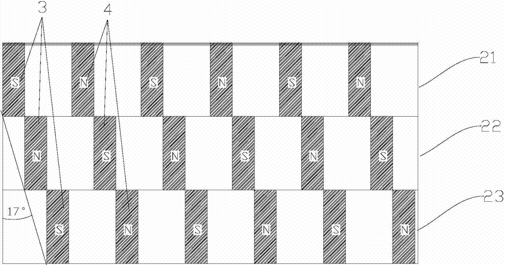
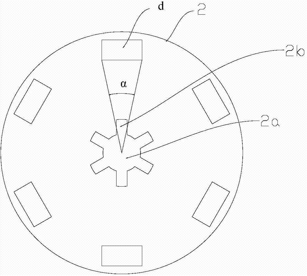
[0025] figure 1 The rotor in the first embodiment of the present invention is shown, which is mainly used to cooperate with the skewed stator to form the motor. Also refer to figure 2 , the rotor includes a rotating shaft 1 , a rotor yoke 2 , a plurality of first permanent magnet groups 3 and a plurality of second permanent magnet groups 4 . A plurality of first permanent magnet groups 3 and a plurality of second permanent magnet groups 4 are alternately distributed at equal intervals along the circumferential direction of the rotor yoke 2, and the first permanent magnet groups 3 and the second permanent magnet groups 4 are arranged in a Projections on a plane perpendicular to axis 1 are adjacent and their edges coincide.

[0026] The rotor yoke 2 is approximately cylindrical and includes a first rotor yoke 21 , a second rotor yoke 22 and a third rotor yoke 23 which are sequentially sleeved on the rotating shaft 1 . The first rotor yoke 21 , the second rotor yoke 22 and th...


PUM


Abstract

The invention provides a rotor and a motor comprising the same. The rotor comprises a rotating shaft, a rotor magnetic conduction yoke, multiple first permanent magnet groups and multiple second permanent magnet groups, wherein the multiple first permanent magnet groups and the multiple second permanent magnet groups are distributed alternately at equal intervals in the circumferential direction of the rotor magnetic conduction yoke, projections of the first permanent magnet groups and the second permanent magnet groups in a plane perpendicular to the rotating shaft are adjacent, and edges of the projections are overlapped. The rotor and the motor comprising the same have the benefits that torque pulsation caused by electromagnetic factors is reduced, and external work of torque is increased, so that the power utilization efficiency of the motor is improved, and energy resources are saved.

Description

technical field [0001] The invention relates to the electromagnetic field, in particular to a rotor and a motor with the rotor. Background technique [0002] The brushless permanent magnet brushless motor in the prior art will generate strong pulsating torque due to electromagnetic factors, the influence of cogging, current commutation, and electromagnetic reaction. There is also torque ripple caused by electromagnetic factors. Electromagnetic torque ripple is a torque ripple caused by the interaction between stator current and rotor magnetic field. It is directly related to the current waveform, back electromotive force waveform, and the distribution of air gap flux density. Ideally, the stator current is a square wave, the back electromotive force waveform is a trapezoidal wave, the width of the flat top is 120° electrical angle, and the electromagnetic torque is a constant value. However, due to design and manufacturing reasons in the actual motor, the back electromotive ...

Claims


Application Information

Patent Timeline
Patent Type & Authority Applications(China)
IPC IPC(8): H02K1/27
CPCH02K1/276H02K1/28H02K3/28H02K16/02H02K21/14H02K2201/06H02K1/16
Inventor 陈宏坤张辉明
Owner SHENZHEN TIANTIAN NEW ENERGY TECH
Why Eureka
Try Eureka