Full-magnetic power machine with electromagnetic pulse regulation magnetic flux device

A technology of electromagnetic pulse and magnetic flux, which is applied to electromechanical devices, circuit devices, battery circuit devices, etc.

Inactive Publication Date: 2015-07-15
章宪
View PDF0 Cites 0 Cited by
  • Summary
  • Abstract
  • Description
  • Claims
  • Application Information

AI Technical Summary

Problems solved by technology

[0002] At present, the development of equipment that converts the magnetic energy of rare earth NdFeB alloy super permanent magnets into mechanical energy is very urgent. During the development process, new technical problems will continue to be discovered in the entire application system, such as: using rare earth for the rotor and stator of the motor The permanent magnet becomes an all-magnetic power machine, but which method is the most suitable to break the balance of the magnetic field? The traditional motor uses a large-capacity battery pack for charging and discharging, and needs to be equipped with a large number of batteries, resulting in a heavy overall quality, and the battery pack has a short service life after being fully charged each time, and requires frequent charging, which limits the scope of use. How to find a way to extend the use Cycle method? The above problems can be explored from the way of traditional motor work to explore innovative methods, and make new technological inventions and innovative solutions

Method used


Image

  • Full-magnetic power machine with electromagnetic pulse regulation magnetic flux device
  • Full-magnetic power machine with electromagnetic pulse regulation magnetic flux device
  • Full-magnetic power machine with electromagnetic pulse regulation magnetic flux device

Examples


example 2

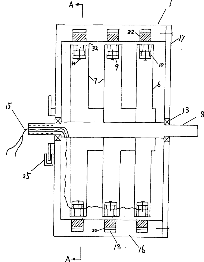
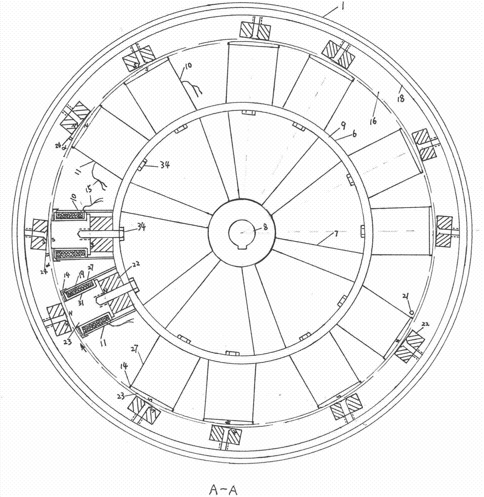
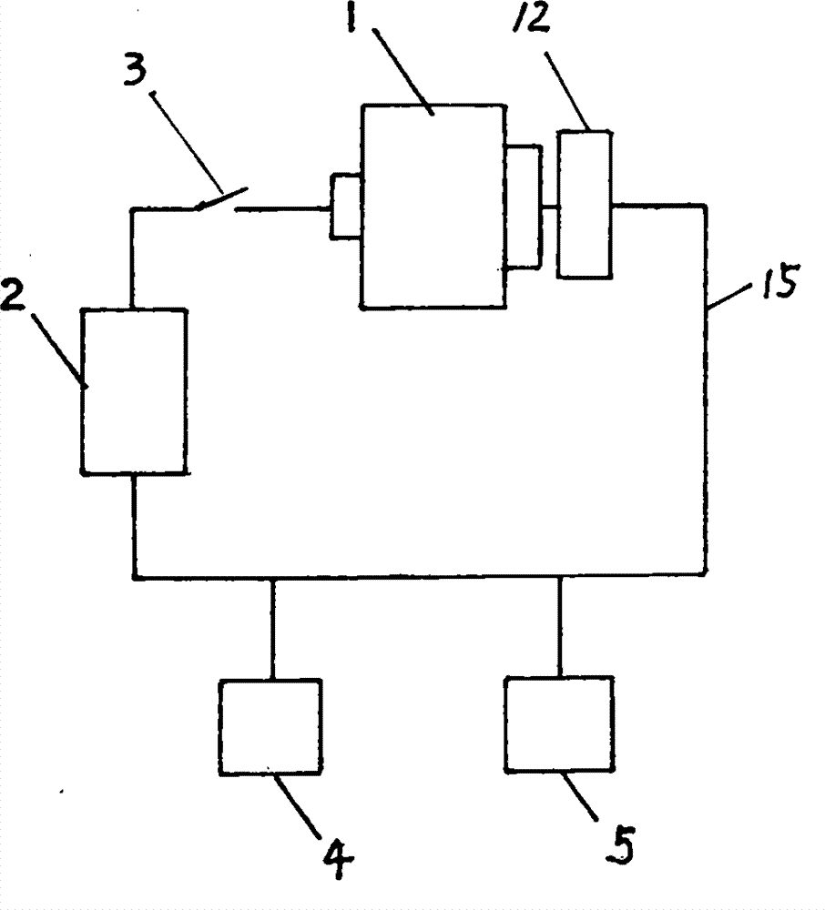
[0015] Example 2: For another type of full-magnetic power machine 1 with an electromagnetic pulse control magnetic flux device with a fixed-rotating inner-shell housing, including an inner turntable 16, a fixed housing 33, an electromagnetic induction pulse programming controller 2, a composite magnetic head 10, 11 , Operating switch 4, energy storage and discharge assembly 5, the main shaft 8 of the inner turntable 16 is equipped with a number of turntables 16, and each turntable 16 is installed with a permanent magnet 22 and a turntable iron ring 18 to form a number of closures on the turntable 16 Magnetic circuit, the turntable iron ring 18 on each turntable 16 is connected to the other magnetic pole of the permanent magnet 22 and the composite magnetic heads 10 and 11 on the fixed housing 33 are dynamically paired accordingly. The stator iron ring 9 on the fixed housing 33 is combined with several composite One end of the magnetic heads 10 and 11 is installed and connected t...


PUM


Abstract

The invention provides a full-magnetic power machine with an electromagnetic pulse regulation magnetic flux device. The full-magnetic power machine is of a rotary outer shell inner stator type or outer shell fixed rotary inner pivot type, and comprises a stator, a rotary disc, the electromagnetic pulse regulation magnetic flux device, combined records, a generator, a speed regulator and an electricity storage and discharging assembly. A plurality of permanent magnets are installed on the surface of the stator and form a closed magnetic circuit with a stator iron hoop, the U-shaped combined records are installed on the stator iron hoop, the electricity storage and discharging assembly supplies electricity so that a magnetic motor can be started and operate the generator to charge the electricity storage and discharging assembly, the pulse regulation device generates a controllable instant induction electromagnetic field to play a variable magnetic effect in the operation process, and the generated magnetic field is overlapped with the interference phenomenon to reduce magnetic resistance, so that the permanent magnet correspondingly installed on the rotary disc can smoothly and continuously rotate under the magnetic energy action. The electricity storage and discharging assembly needs to be supplemented with electricity according to an electricity quantity indicator light, the use time of the electricity storage and discharging assembly after each time electricity charging is prolonged, the number of traditional storage batteries is reduced, and the full-magnetic power machine adopts environment-friendly and reproducible novel energy.

Description

Technical field [0001] The invention relates to the technical field of application systems for converting magnetic energy into mechanical energy of rare earth permanent magnets. Background technique [0002] At present, the development of equipment that converts the magnetic energy of the rare earth neodymium iron boron alloy super permanent magnets into mechanical energy is very urgent. During the development process, new technical problems will be discovered in the entire application system, such as: the use of rare earths in the rotor and stator of the motor The permanent magnet becomes a full-magnetic power machine, but what method is most suitable to break the balance of the Huan magnetic field? Traditional motors use large-capacity battery packs for charging and discharging and need to be equipped with a large number of batteries, resulting in a very heavy overall quality, and the battery pack has a short service life after each full charge. Frequent charging limits the sco...

Claims


Application Information

Patent Timeline
Patent Type & Authority Applications(China)
IPC IPC(8): H02N11/00H02J7/14
CPCH02K53/00H02K99/20H02K1/17H02K1/18H02K1/278H02K25/00H02P7/282
Inventor 章宪章文婕朱小燕
Owner 章宪
Why Eureka
Try Eureka