
Dust collection electrode back-flushing filtering electrostatic precipitator

A dust collecting pole and electrostatic precipitator technology, applied in electrostatic separation, electrode structure, electrode cleaning, etc., can solve the problems of increasing the resistance of the dust collector, reducing the advantages of equipment, and not being able to solve the problem of dust removal well, so as to improve the dust removal efficiency , Solve the effect of secondary dust

Active Publication Date: 2015-07-22
SHANDONG PROVINCE METALLURGICAL ENG CO LTD
View PDF13 Cites 8 Cited by
  • Summary
  • Abstract
  • Description
  • Claims
  • Application Information

AI Technical Summary

Problems solved by technology

However, the metal mesh filter is fixed, and its dust removal has become a difficult point, which cannot solve the dust removal problem well, will increase the resistance of the dust collector, and reduce the advantages of the equipment

Method used


Image

  • Dust collection electrode back-flushing filtering electrostatic precipitator
  • Dust collection electrode back-flushing filtering electrostatic precipitator
  • Dust collection electrode back-flushing filtering electrostatic precipitator

Examples


Embodiment 1

[0037] Example 1, such as Figure 1 to Figure 6 shown.

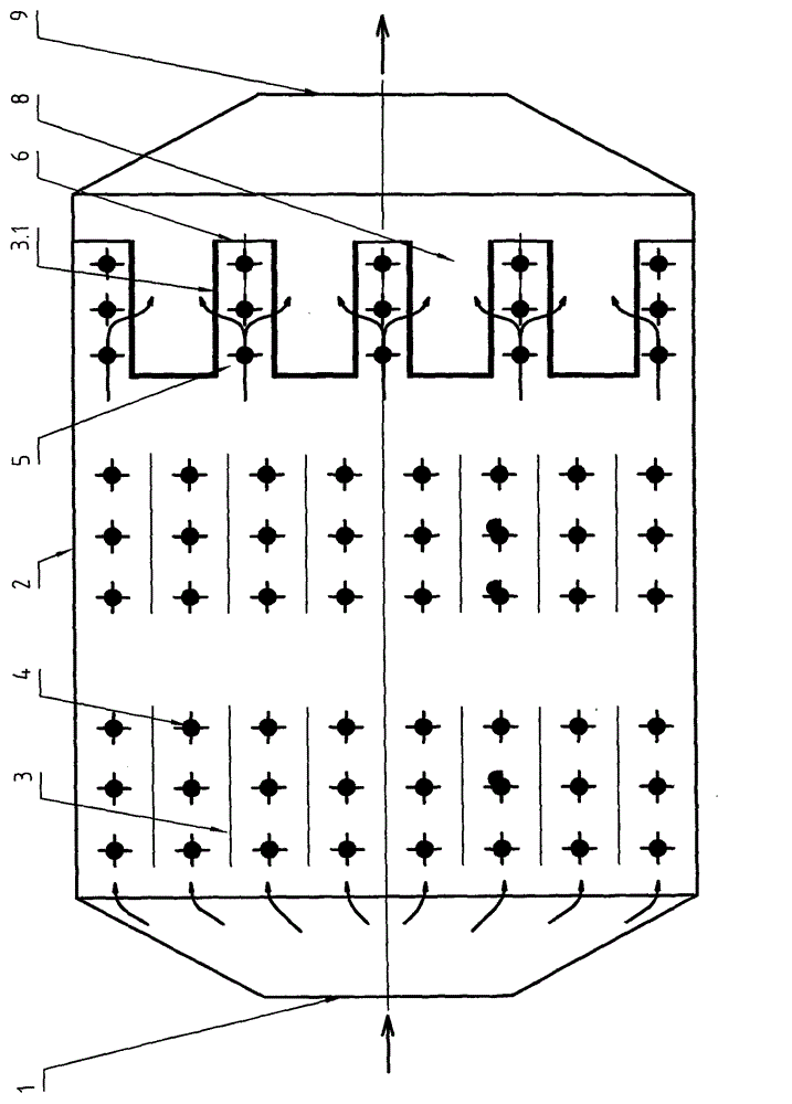
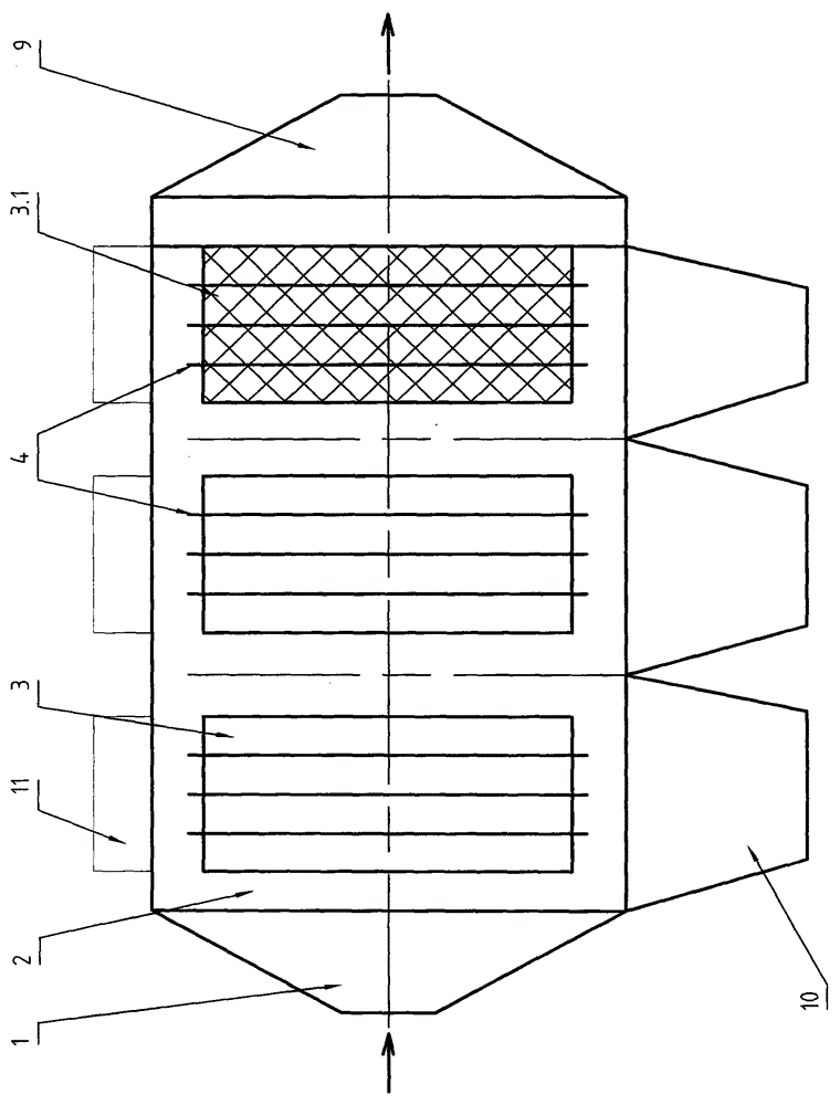
[0038] The dust-collecting electrode blowback filter electrostatic precipitator of the present invention comprises gas inlet 1, housing 2, anode 3, cathode 4, gas outlet 9, ash hopper 10, power supply system 11 etc.; Anode 3 is plate-type dust-collecting electrode (comprising C-shaped plate, Z-shaped plate, etc.), there are multiple anodes 3 along the length direction of the shell 2, and there are multiple rows of anodes 3 along the width direction of the shell 2, and cathodes 4 are arranged between the anodes 3; the high-voltage power supply system supplies the anodes 3 and The cathode 4 supplies power; the anode 3 and the cathode 4 are fixed on the frame of the housing 2 through a hanging device (not shown).

[0039] The anode constitutes the dust collection pole, and in the direction of the flow of the dust-laden gas, at least a part of the dust collection pole at the rear of the anode 3 is a mesh dust collection pol...

Embodiment 2

[0044] Example 2, Figure 7 shown.

[0045] This embodiment is a change carried out on the basis of Embodiment 1, the difference is:

[0046] In the flow direction of the dusty gas, all the dust collecting poles are mesh dust collecting poles 3.1. In the width direction of the casing 2, there are two rows of mesh dust collecting poles 3.1.


PUM


Abstract

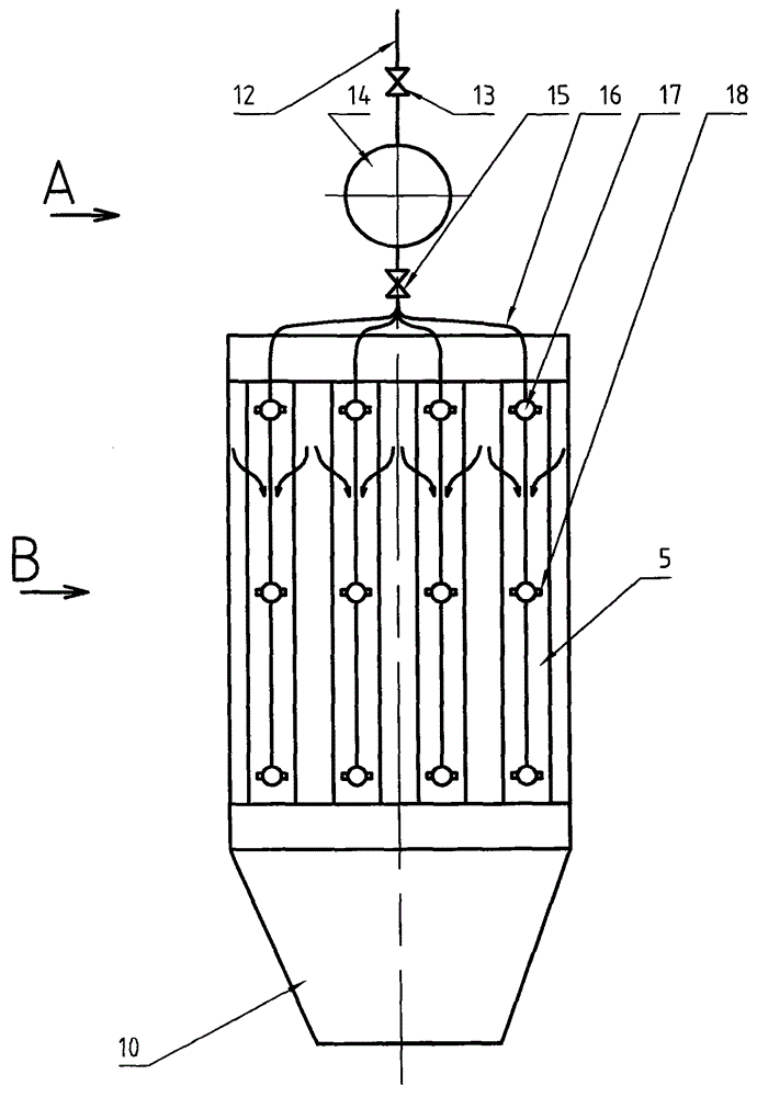
The invention belongs to the field of environmental protection, and provides a dust collection electrode back-flushing filtering electrostatic precipitator. The electrostatic precipitator comprises a housing, dust buckets, an air inlet, an air outlet, negative electrodes, positive electrodes, a power supply system, and the like. In a dust-contained air flowing direction, at least a part of dust collection electrodes at the rear part of the dust collection electrodes are meshy dust collection electrodes; the meshy dust collection electrodes are arranged in parallel and are connected to separators to form meshy dust collection electrode air-intake spaces and meshy dust collection electrode air-exhaust spaces; and the negative electrodes are arranged in the meshy dust collection electrode air-intake spaces among the meshy dust collection electrodes. An injection box is arranged outside the housing, and is provided with a plurality of injection branch pipes and injection valves; each meshy dust collection electrode air-exhaust space is internally provided with one injection pipe; and each injection pipe having a branch pipe extending upwards out of the housing and connecting the injection branch pipes of the injection box. According to the invention, electric precipitation is effectively combined with filtering precipitation, so that the dust removing efficiency is greatly improved; the problem of dust cleaning of meshy dust collection electrodes is effectively solved; and the dust collection electrode back-flushing filtering electrostatic precipitator is suitable for reconstruction and renovation of a project.

Description

technical field [0001] The invention relates to an industrial flue gas dedusting device and belongs to the field of environmental protection. Background technique [0002] Industrial production in all walks of life produces a large amount of dust-containing gas, and the direct discharge of dust-containing gas into the atmosphere will cause serious environmental pollution. Therefore, the dust-containing gas generally needs to go through dust removal facilities to remove a large amount of dust, and the dust content of the gas reaches the national standard. atmospheric emissions. [0003] Dust removal facilities are divided into coarse dust removal facilities and fine dust removal facilities. Fine dust removal facilities mainly include bag filter and electrostatic precipitator. Electrostatic precipitator is widely used because of its small resistance, high dust removal efficiency and temperature resistance. [0004] However, the cost of electrostatic precipitator is high, and ...

Claims


Application Information

Patent Timeline
IPC IPC(8): B03C3/47B03C3/80
Inventor 姚朝胜
Owner SHANDONG PROVINCE METALLURGICAL ENG CO LTD
Learn More