Casting die and casting process of die-casting machine rubber injection head plate

A technology of injection head plate and casting mold, which is applied in the direction of manufacturing tools, casting molding equipment, casting molds, etc., can solve the problems of unsatisfactory improvement, irregular casting structure, uneven thickness, etc., and achieve the elimination of shrinkage cavity and porosity Defects, reducing the probability of shrinkage, and refining the effect of the matrix structure

Active Publication Date: 2015-07-22
GUANGDONG HENGCHENG TECH
View PDF6 Cites 0 Cited by
  • Summary
  • Abstract
  • Description
  • Claims
  • Application Information

AI Technical Summary

Problems solved by technology

[0002] Injection head plate (such as Figure 1 to Figure 3 ) is the key core component of the die-casting machine, which belongs to the high wear-resistant and sealing part of the hydraulic brake. Regular (uneven thickness), in actual production, shrinkage cavity shrinkage occurs at 2 / 3 of the through hole (such as Figure 4 ), oil leakage occurred to varying degrees after the machine was installed or leaked during a certain period of machine operation, causing the casting to be scrapped, and the process yield was only 68%, and many improvements did not achieve the desired effect
[0003] The casting mold of the injection head plate is as Figure 5 , Image 6 As shown, the molten iron enters the cavity from the front of the cavity, the pouring process of the casting does not meet the structural requirements of the casting, the wall thickness of the corresponding surface of the inner runner is large, and the cooling rate is slow, which is the main cause of shrinkage and shrinkage.

Method used


Image

  • Casting die and casting process of die-casting machine rubber injection head plate
  • Casting die and casting process of die-casting machine rubber injection head plate
  • Casting die and casting process of die-casting machine rubber injection head plate

Examples


Embodiment Construction

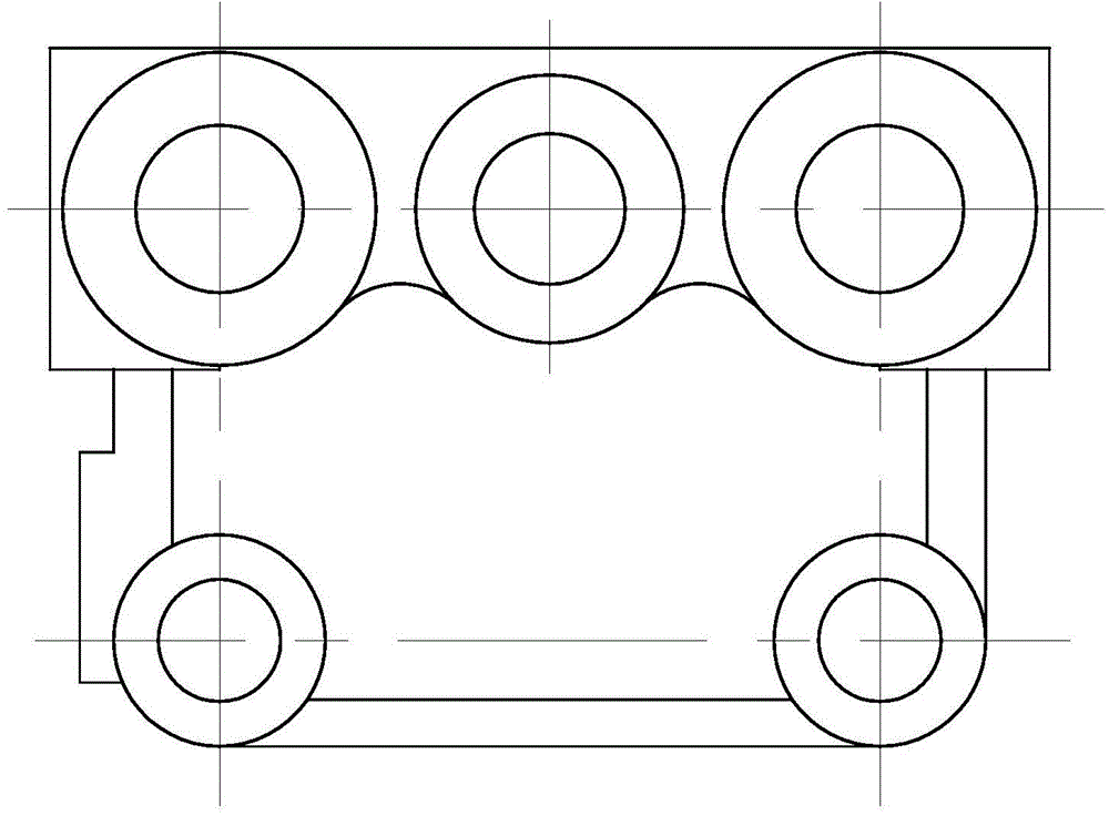
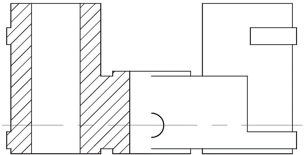
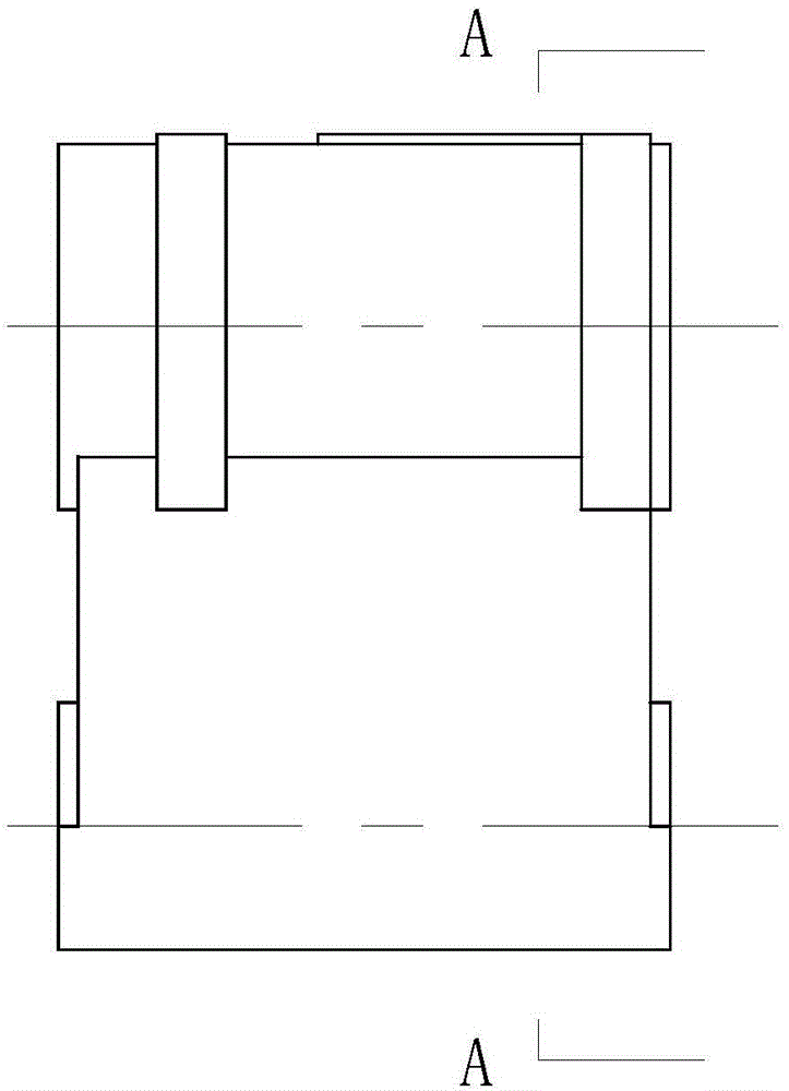
[0028] refer to Figure 7 to Figure 9 , Figure 7 to Figure 9 It is a structural schematic diagram of a specific embodiment of the present invention. As shown in the figure, the casting mold of the injection head plate of the die-casting machine includes a mold body, and the mold body includes an upper mold 1 and a lower mold 2, and the upper mold 1 and the lower mold 2 are provided with at least two cavities 3 corresponding to the injection head plate, and a sprue 51 is provided on the upper mold 1, and the sprue 51 is connected to both sides of the cavity 3 through a runner 52, In addition, two ends of the runner 52 are respectively connected to the bottoms on both sides of the cavity 3 through an inrunner 53 , and the upper end of the cavity 3 is also provided with a vent hole 54 .

[0029] Preferably, as shown in the figure, there are two cavities 3 arranged symmetrically, and the sprue and runner 52 are arranged between the two cavities 3 .

[0030] In order to balance ...


PUM


Abstract

The invention discloses a casting die and a casting process of a die-casting machine rubber injection head plate. The casting die comprises a die body, wherein the die body comprises an upper die and a lower die; at least two cavities which correspond to the rubber injection head plate are formed between the upper die and the lower die; a gate sprue is formed in the upper die, and is communicated with two sides of the cavities through cross gates; two ends of each cross gate are respectively communicated with the bottoms of two sides of the cavities through the ingates; and exhaust holes are also formed in the upper ends of the cavities. The ingates are communicated with the side surfaces of the cavities, and the walls corresponding to the ingates are not thick, so that cooling balance is formed, and the simultaneous solidification effect is reached. Through utilization of an instantaneous flow inoculation process, the matrix structure is refined; the compactness is improved; and the shrinkage rate is reduced. Due to the adoption of the improved process, the defect of shrinkage of shrinkage cavities is basically removed; the oil leakage rate after installation is only 1%-1.5%; the yield is greatly improved; and obvious economic benefits are obtained.

Description

technical field [0001] The invention relates to a casting mold and a casting process for a plastic injection head plate of a die-casting machine. Background technique [0002] Injection head plate (such as Figure 1 to Figure 3 ) is the key core component of the die-casting machine, which belongs to the high wear-resistant and sealing parts of the hydraulic brake. Regular (uneven thickness), in actual production, shrinkage cavity shrinkage occurs at 2 / 3 of the through hole (such as Figure 4 ), oil leakage occurred to varying degrees after installation or leaked during a certain period of machine operation, resulting in scrapped castings, and the process yield was only 68%, and many improvements failed to achieve the desired effect. [0003] The casting mold of the injection head plate is as Figure 5 , Figure 6 As shown, the molten iron enters the cavity from the front of the cavity, the pouring process of the casting does not meet the structural requirements of the cas...

Claims


Application Information

Patent Timeline
Patent Type & Authority Applications(China)
IPC IPC(8): B22C9/02C22C33/08B22D17/20
CPCB22C9/02B22D17/20C22C33/08
Inventor 王和迪
Owner GUANGDONG HENGCHENG TECH
Why Eureka
Try Eureka