
Steel reinforcement arrangement structure of steel structure-concrete slag combined bridge

A technology for concrete slabs and steel structures, applied in bridges, bridge materials, bridge construction, etc., can solve the problems of material waste, inability to resist lateral bending moments in local areas, etc., and achieve the effect of simple construction and improved concrete bearing capacity.

Active Publication Date: 2015-07-22
中铁桥隧技术有限公司 +1
View PDF8 Cites 2 Cited by
  • Summary
  • Abstract
  • Description
  • Claims
  • Application Information

AI Technical Summary

Problems solved by technology

In the Eurocode, an independent vertical hoop is added in this area. Although the number of shear reinforcement of the bottom slab is increased, the upper edge of the hoop of the top slab is a waste of material
The method in America is to increase the number of open U-shaped stirrups, which also increases the number of shear reinforcement in the bottom plate, but the U-shaped reinforcement is open on the top surface and cannot resist the lateral bending moment in a local area.

Method used


Image

  • Steel reinforcement arrangement structure of steel structure-concrete slag combined bridge
  • Steel reinforcement arrangement structure of steel structure-concrete slag combined bridge
  • Steel reinforcement arrangement structure of steel structure-concrete slag combined bridge

Examples


Embodiment Construction

[0013] The present invention will be described in detail below with reference to the accompanying drawings.

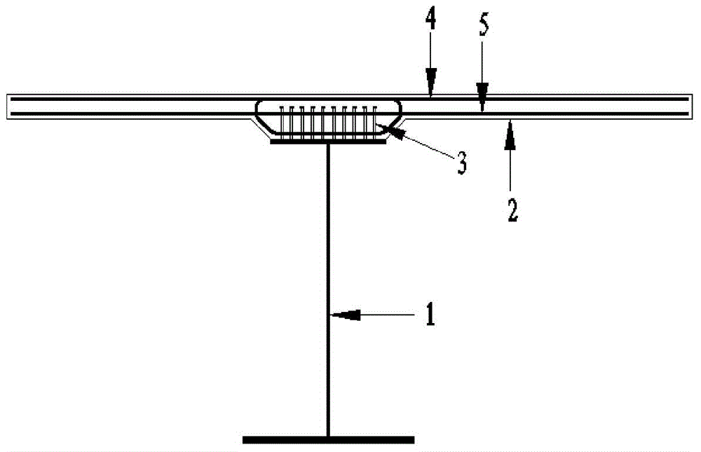
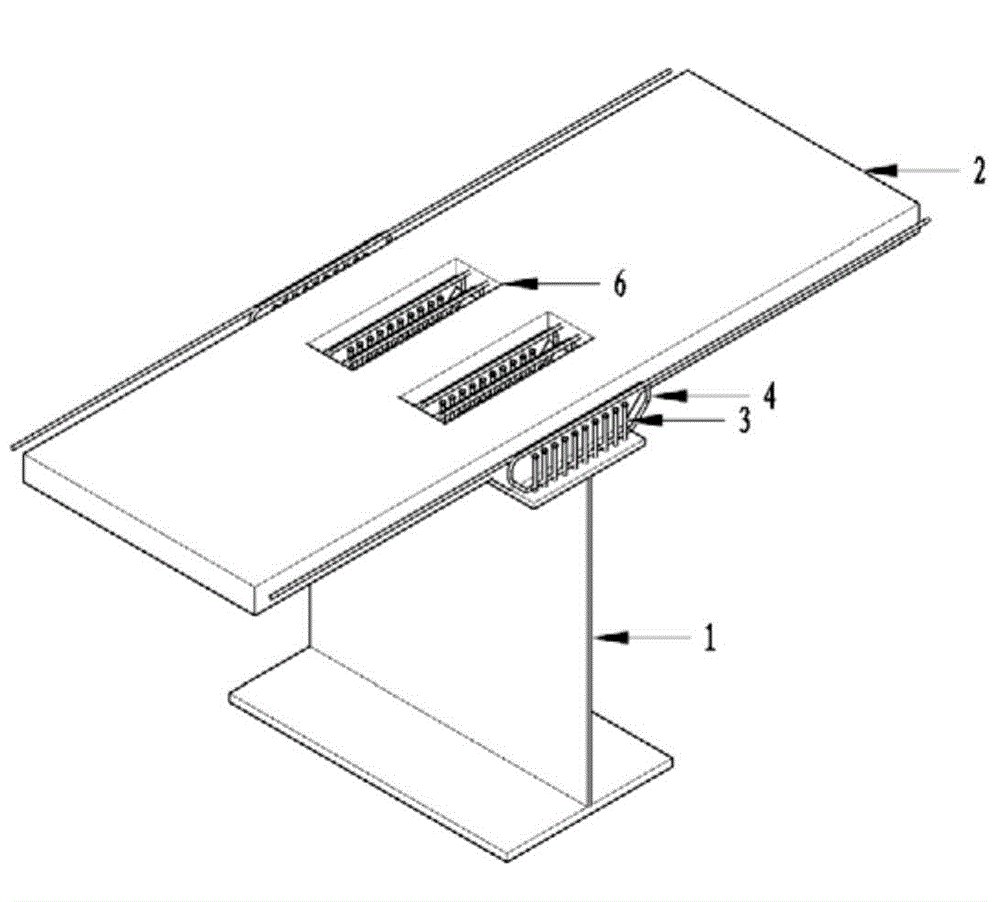
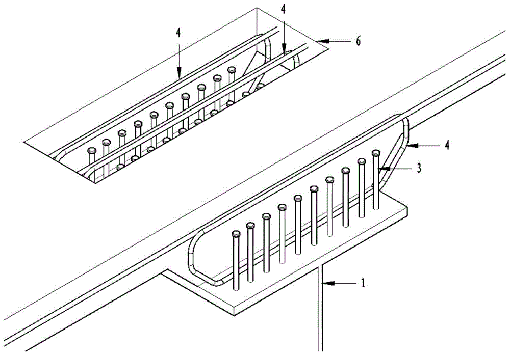
[0014] refer to figure 1 , figure 2 , image 3 , Figure 4 , the transverse main reinforcement is bent at the joint notch to form a hoop 4, and extends over the top surface of the steel structure 1, the hoop 4 and the transverse main reinforcement 5 on it form an integral tendon structure, and the overall tendon structure and the shear stud in the joint notch 6 3 Stagger the layout to form a steel reinforcement structure, and the steel reinforcement structure is simultaneously used as a roof beam, combined notch stirrups, and a bottom beam beam. According to the specific construction requirements, the steel reinforcement structure adopts different spacing arrangements.

[0015] When adopting the construction of the present invention, the integral reinforcement structure formed by the hoop 4 and the transverse main reinforcement 5 thereon is manufactured in a facto...


PUM


Abstract

The invention relates to a steel reinforcement arrangement structure of a steel structure-concrete slag combined bridge. Transverse main reinforcements are bent to form hoops at combined notches and extend over the top surface of a steel structure, the hoops and the transverse main reinforcements on the hoops form overall rib structures, the overall rib structures and shear pins inside the notches are arranged in a staggered mode to form the steel reinforcement arrangement structure, and the steel reinforcement arrangement structure serves as a top slab tendon, a combined notch reinforcement stirrup and a bottom slab tendon. According to detailed construction requirements, steel reinforcement arrangement structures are arranged at different intervals. Cast-in-place concrete is used for pouring the combined notches, the shear pins and the steel reinforcement arrangement structures into a bridge deck slab. Transverse closed steel reinforcement hoop concrete regions formed at the combined positions can improve the bearing capacity of the concrete. The transverse steel reinforcements continuously pass through the combined notches without affecting transverse stress performance, and the steel reinforcement arrangement structure is safer and more reliable because peak value hogging moment is borne by the two main reinforcements. Construction is easy and convenient, and because each hoop is formed by a complete steel reinforcement, the steel reinforcement arrangement structure can be better adapted to influences caused by construction errors.

Description

technical field [0001] The invention relates to a steel bar reinforcement structure of a steel structure-concrete slab combined bridge, which is mainly applied in the field of highway bridges, railway bridges and other building structures using steel-concrete combination. Background technique [0002] The combination notch is a complex stress area of ​​the steel-concrete composite structure, which is usually equipped with shear studs, longitudinal common steel bars, transverse common steel bars, transverse prestressed steel bars and cast-in-place concrete. [0003] After the bridge is completed, the transverse reinforcement not only needs to bear the longitudinal stress brought by the bridge deck as the roof of the first system, but also be affected by the transverse bending moment and vertical shear force brought by the vehicle load. Therefore, the transverse reinforcement in this area often needs to consider the shear resistance needs of the interaction with the shear stud...

Claims


Application Information

Patent Timeline
IPC IPC(8): E01D2/00
CPCE01D2/00E01D2101/268
Inventor 胥润东廖慕捷侯鹏飞梅新咏杨建军刘小林周杰肖小艳
Owner 中铁桥隧技术有限公司
Learn More