Design method for heat dissipation system of wind turbine generator set under severe environment and heat dissipation system

A technology for wind turbines and cooling systems, applied in wind turbine components, wind motor combinations, wind engines, etc., can solve problems such as reducing the amount of cold air entering the radiator, failing to achieve the cooling effect, and affecting the normal operation of the generator set. Achieve the effect of ensuring heat dissipation and avoiding blockage

Active Publication Date: 2015-07-22
CSIC CHONGQING HAIZHUANG WINDPOWER EQUIP
View PDF6 Cites 3 Cited by
  • Summary
  • Abstract
  • Description
  • Claims
  • Application Information

AI Technical Summary

Problems solved by technology

Specifically reflected in: Suspended matter (flying catkins, flying dust, coal ash, etc.) will be adsorbed at the air suction port of the radiator. After long-term operation, more and more suspended matter will be

Method used


Image

  • Design method for heat dissipation system of wind turbine generator set under severe environment and heat dissipation system

Examples


Embodiment 1

[0024] A design method for the heat dissipation system of a wind power generating set in a harsh environment, comprising the following steps:

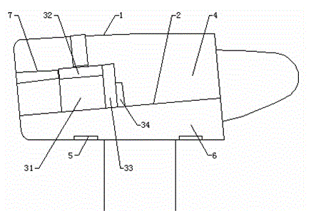
[0025] (1) Construct the outer air duct of the cooling system: the outer air duct of the cooling system is formed in the space between the wind turbine cabin shell and the radiator of each component of the wind turbine. The components of the wind turbine include a gearbox, a generator, a frequency conversion devices and control cabinets;

[0026] (2) Determine the air suction volume of the external air duct: the air suction volume Q is the sum of the cooling air volume required by each radiator to reach the rated cooling temperature, specifically: gear box radiator, generator radiator, inverter radiator and control cabinet cooling The cooling air volume required to reach the rated cooling temperature is Q1, Q2, Q3 and Q4 respectively, Q=Q1+Q2+Q3+Q4;

[0027] (3) Set the wind speed V of the air inlet of the outer air duct 0 =3.8 m / s; ...

Embodiment 2

[0033] A design method for the heat dissipation system of a wind power generating set in a harsh environment, comprising the following steps:

[0034] (1) Construct the outer air duct of the cooling system: the outer air duct of the cooling system is formed in the space between the wind turbine cabin shell and the radiator of each component of the wind turbine. The wind turbine components include generators, frequency converters and control cabinet;

[0035] (2) Determine the air suction volume of the external air duct: the air suction volume Q is the sum of the cooling air volume required by each radiator to reach the rated cooling temperature, specifically: the radiator of the generator, the radiator of the frequency converter and the radiator of the control cabinet reach the rated cooling temperature The required cooling air volumes are Q2, Q3 and Q4 respectively, Q=Q2+Q3+Q4;

[0036] (3) Set the wind speed V of the air inlet of the outer air duct 0 =3 m / s;

[0037] (4) ...


PUM


Abstract

The invention discloses a design method for a heat dissipation system of a wind turbine generator set under a severe environment and the heat dissipation system. An outer air duct is added to a heat dissipation system of an original wind turbine generator set through the five steps of constructing the outer air duct of the heat dissipation system, determining the air volume of the outer air duct, determining the air speed of an air inlet of the outer air duct, determining the area of the air inlet of the outer air duct and forming the air inlet. The air speed of the air inlet is made to be 3 m/s-4 m/s by controlling the area of the air inlet, so that little or no suspended matter is sucked into the outer air duct. Radiators of the original heat dissipation system suck cold air through the outer air duct, and therefore exhaust inlets of the radiators cannot be blocked, the cold air intake volume and the heat dissipation effect are guaranteed, and the wind turbine generator set can meet use requirements under the severe environment.

Description

technical field [0001] The invention relates to the field of wind power generation, in particular to a design method and the heat dissipation system of a wind power generating set heat dissipation system in harsh environments. Background technique [0002] The "Thirteenth Five-Year Plan" in various fields of new energy is being compiled, and wind power will gradually change its current status as an "alternative energy" widely regarded as an "alternative energy source" and rise to become the main body of the country's energy structure adjustment in the future. According to the planning idea, during the "Thirteenth Five-Year Plan" period, the newly installed capacity of domestic wind power will reach 100 million kilowatts, with an average annual increase of 20 million kilowatts. The central and eastern resource areas with medium and low wind speeds will add 30 million kilowatts, and offshore wind power will add 10 million kilowatts. [0003] Regions rich in wind energy resour...

Claims


Application Information

Patent Timeline
IPC IPC(8): F03D11/00
CPCF05B2260/20F03D80/80F03D80/60F05B2260/221Y02E10/72Y02T50/60F03D9/25F03D80/88
Inventor 周祖田张万军陶友传宁潞林王亚军黄金余
Owner CSIC CHONGQING HAIZHUANG WINDPOWER EQUIP
Why Eureka
Try Eureka