Fuel gas valve

A gas valve and valve core technology, applied in multi-port valves, valve devices, valve details, etc., can solve problems such as misoperation, achieve the effects of convenient and simple adjustment, reduce misoperation, and improve production efficiency

Active Publication Date: 2015-07-22
NINGBO CHAOYANG HOUSEHOLD GAS STOVES
View PDF8 Cites 10 Cited by
  • Summary
  • Abstract
  • Description
  • Claims
  • Application Information

AI Technical Summary

Problems solved by technology

However, there is only one air intake channel for such replacement and adjustment, which requires professional personnel, otherwise it is easy to cause danger due to misoperation, and the production requirements are high, requiring higher precision in the processing of gas valves

Method used


Image

  • Fuel gas valve
  • Fuel gas valve
  • Fuel gas valve

Examples


Embodiment Construction

[0030] The present invention will be further described in detail below in conjunction with the accompanying drawings and embodiments.

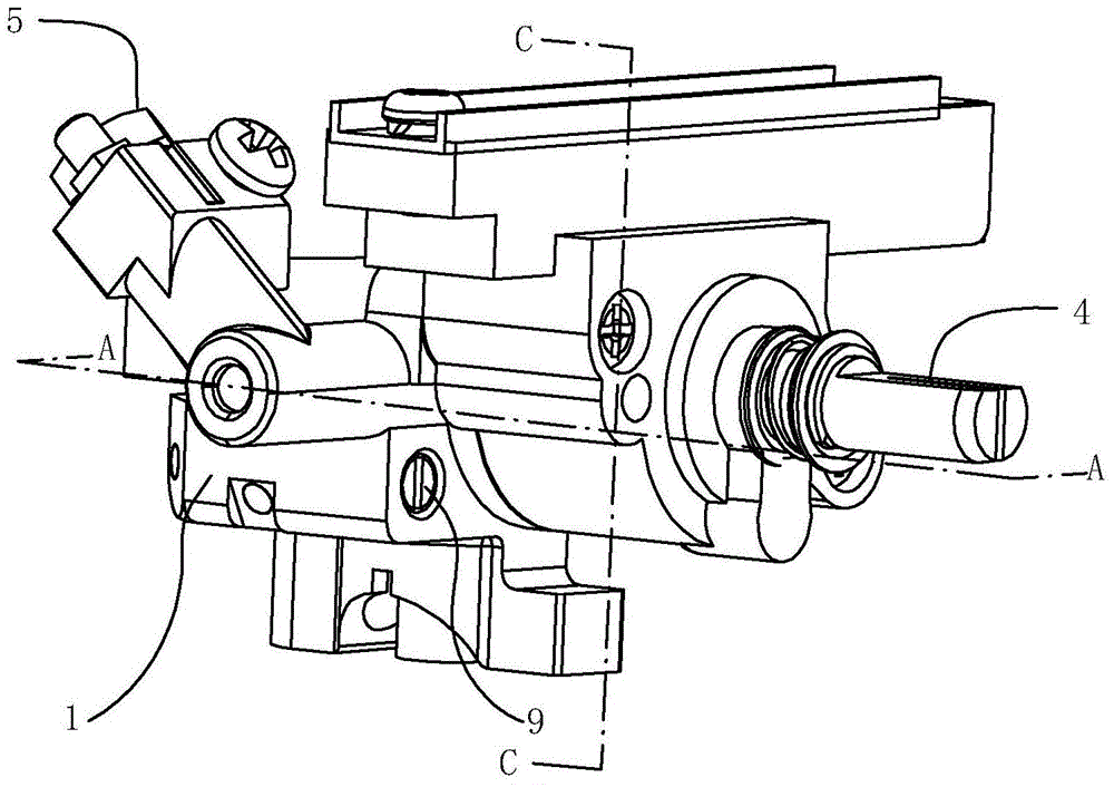
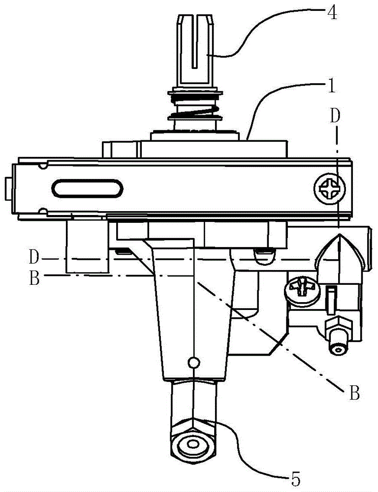
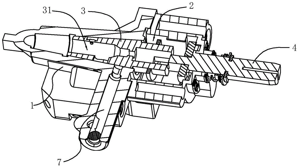
[0031] Such as Figure 1-6 As shown, the gas valve of the embodiment of the present invention includes a valve body 1, a cavity 2 located in the valve body 1, and a valve core 3 located in the cavity 2, the valve core 3 is closely matched with the cavity 2, and the valve The core 3 can rotate around its own axial direction in the cavity 2 . The valve core 3 is provided with a ventilation cavity 31 extending along its axial direction, and one end of the valve body 1 is provided with a rotating shaft 4, and the end of the rotating shaft 4 is inserted into the cavity 2 of the valve body 1 and cooperates with the valve core 3 , to drive the valve core 3 to rotate, the other end of the valve body 1 is provided with a nozzle 5 , and the nozzle 5 communicates with the vent chamber 31 in the valve core 3 .

[0032] One side of the valve body 1 is pr...


PUM


Abstract

The invention provides a fuel gas valve comprising a valve body, a valve element and an auxiliary gas intake channel. A gas cavity is formed in the valve element. The side wall, matched with a gas intake channel of the valve body, of the valve element is provided with gas intake holes. The gas intake holes are communicated with the gas cavity in the valve element. The auxiliary intake channel is arranged in the valve body. One end of the auxiliary gas intake channel is communicated with the gas intake channel. The other end of the auxiliary gas intake channel is communicated with the cavity of the valve body. The side wall of the valve element is provided with auxiliary gas intake holes matched with the auxiliary gas intake channel in position. The auxiliary gas intake holes are communicated with the gas cavity in the valve element. The auxiliary gas intake holes and the gas intake holes are staggered in the axial direction and the circumferential direction of the valve element. The fuel gas valve can adjust the flow of fuel gas in a pipeline, so that the fuel gas valve is suitable for different gas sources. The fuel gas valve is provided with the gas intake holes and the auxiliary intake holes separated from the gas intake holes, so that when the flow of the fuel gas is adjusted, the possibility of misoperation is reduced, and the flow of the fuel gas is more convenient and easier to adjust.

Description

technical field [0001] The invention relates to a valve for a gas cooker. Background technique [0002] The gas valve in a gas appliance is a manually operated valve that controls the supply of gas. Ordinary gas valves generally include a valve body with an air inlet passage and an air outlet passage. The valve body is provided with a rotatable valve core. The valve stem that drives the valve core to rotate. The lower end of the valve stem is equipped with a spring that keeps the valve stem moving up and out of the connection with the valve core. The spring is located in the spring chamber on the valve core. To communicate with the large fire hole and the small fire hole of the air inlet passage and the air outlet passage. When in use, the gas outlet channel of the valve body is connected to the gas nozzle through a hose, and the gas nozzle enters the burner of the gas stove. Drive the valve core to rotate, so that the large fire hole on the valve core is connected with t...

Claims


Application Information

Patent Timeline
Patent Type & Authority Applications(China)
IPC IPC(8): F16K5/02F16K5/10
CPCF16K5/02F16K5/10F16K5/103F16K11/083F23K5/007F23K2900/05001F23K2900/05002F23N2241/08F23N2235/24F23K2400/201F23N1/007F16K11/076F16K31/50F16K31/60F23N2235/12
Inventor 李雪亚
Owner NINGBO CHAOYANG HOUSEHOLD GAS STOVES
Why Eureka
Try Eureka