Radiating control method for high-voltage power distribution cabinets

A technology of high-voltage power distribution cabinet and control method, which is applied in the direction of temperature control using electric method, cooling/ventilation of substation/switchgear, electrical components, etc. , to achieve the effect of improving cooling efficiency, not easy to generate, and reducing losses

Active Publication Date: 2015-07-22
NINGXIA KAICHEN ELECTRIC GROUP
View PDF5 Cites 13 Cited by
  • Summary
  • Abstract
  • Description
  • Claims
  • Application Information

AI Technical Summary

Problems solved by technology

[0005] 1. Adopt the scheme of installing a fan in the electrical cabinet. Since the fan will vibrate when it is working, this vibration will be transmitted directly to the electrical components inside it through the cabinet body. When various electrical components are in a vibrating state for a long time, their internal The components are easily damaged, which affects the service life. On the other hand, various connecting lines and contacts are also disengaged due to long-term vibration, causing the entire system to fail. Therefore, there are problems in the scheme of using an internal fan;
[0006] 2. The electrical cabinet is generally placed in the electrical room. If there is no air conditioner in the electrical room, the temperature of the entire electrical room will be very high, especially in summer, because the external air temperature is high, the fan in the electrical cabinet has to work for a long time; Install an air conditioner in the electrical room, and most of the cold air generated by the air conditioner is the energy consumption of the building, that is, the air in the entire electrical room needs to be cooled, so the energy consumption is high, which is not cost-effective;
[0007] 3. The control core in the electrical cabinet: the controller does not have a separate heat dissipation structure. Once the controller fails due to untimely heat dissipation, it will paralyze the entire system and cause immeasurable losses
[0008] Because there are above-mentioned technical problems in prior art, affect use, therefore must improve

Method used


Image

  • Radiating control method for high-voltage power distribution cabinets
  • Radiating control method for high-voltage power distribution cabinets
  • Radiating control method for high-voltage power distribution cabinets

Examples


Embodiment 1

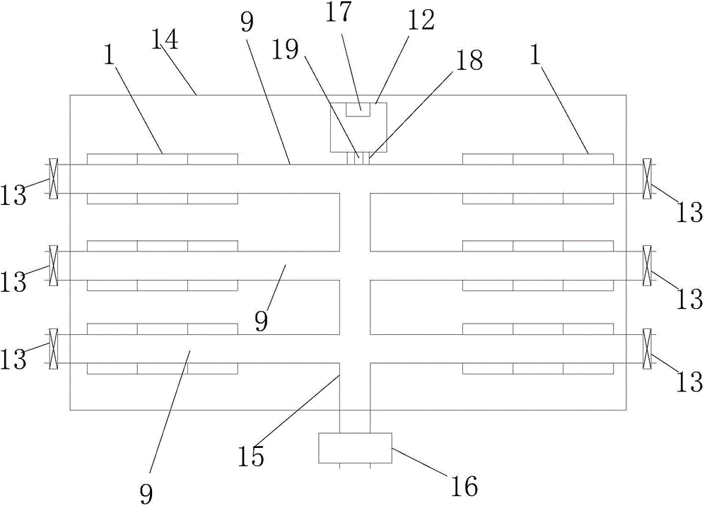
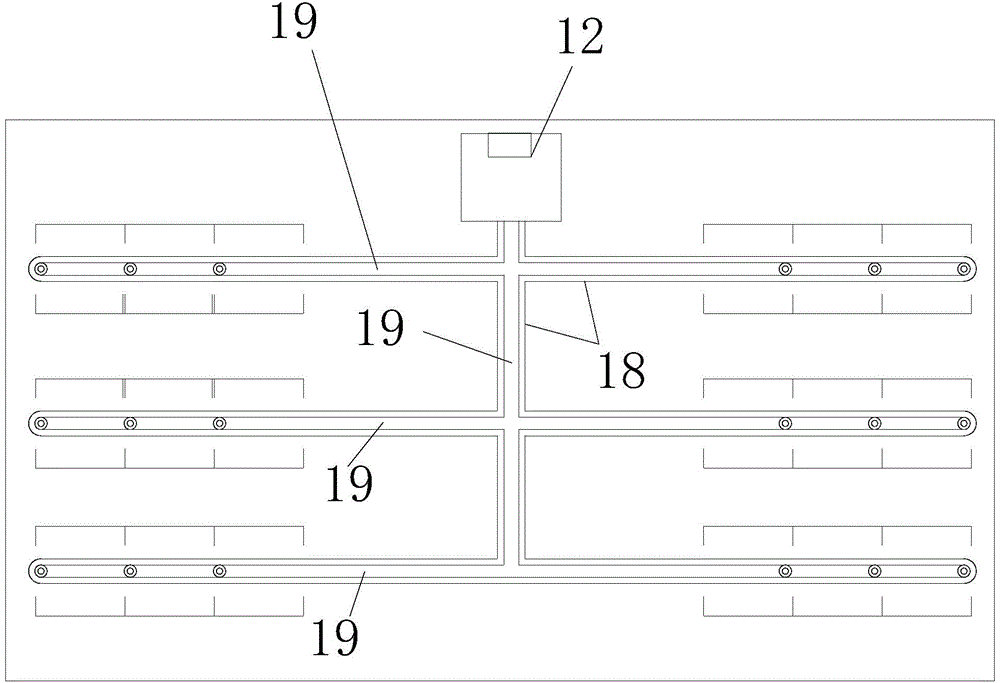
[0034] like figure 1 , 2, 3, and 4, the heat dissipation control method of the high-voltage power distribution cabinet described in this embodiment places the power distribution cabinet 1 in the electrical room 14, and the power distribution cabinet 1 is divided into multiple rows, and each row of power distribution cabinets 1 are distributed in a straight line, and the lower part of each power distribution cabinet 1 is provided with an air inlet 4, and the installation board 3 for installing electrical components is generally provided in the power distribution cabinet 1, and the characteristic is that: above each row of power distribution cabinets 1 Both ends are provided with an air duct 9 outside the electrical room 14, and the air outlet 11 on the top of the power distribution cabinet 1 communicates with the air duct 9 through the heat dissipation pipe 12; With technology, the simplest damper can be an electric flapper valve. The damper 13 is usually in an open state, and...

Embodiment 2

[0042] like Figure 5 , 6 , 7, and 8, the heat dissipation control method of the high-voltage power distribution cabinet described in this embodiment is different from the method described in Embodiment 1 in that:

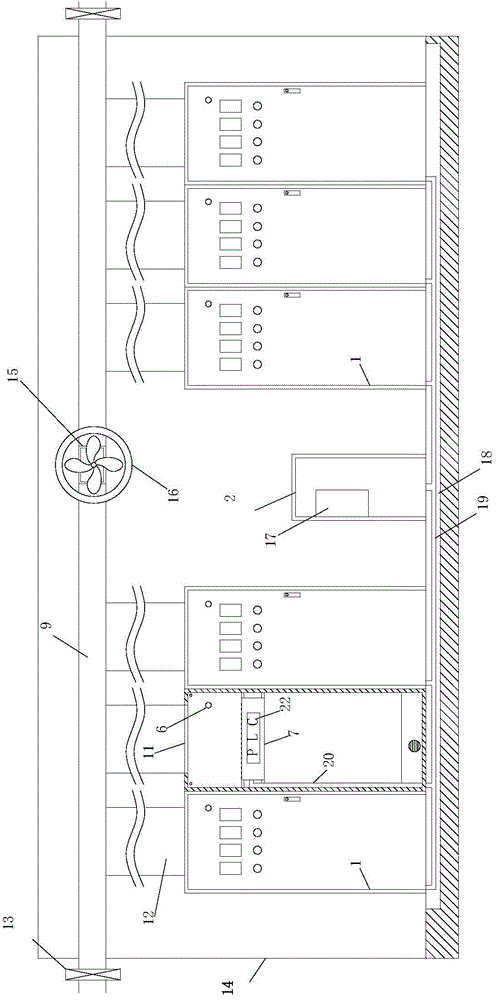
[0043] Each power distribution cabinet 1 is also provided with a cold air cover 8, which is covered with air outlet holes 10, and the cold air cover 8 communicates with the cold air pipe 19 through the second pipeline 21, and the second pipeline 21 is provided with a cold air valve 23; After the cold air valve 23 is opened, the cold air in the air cooler 2 is released through the cold air cover 8 to cool down the power distribution cabinet 1 .

[0044] A temperature sensor 6 is provided in each power distribution cabinet 1, a fan 5 is provided on the air inlet 4 at the bottom of each power distribution cabinet 1, and a master controller 24 is provided in the air-conditioning cabinet 2, and each power distribution cabinet The signals of the temperature sensor 6 in...


PUM


Abstract

The invention discloses a radiating control method for high-voltage power distribution cabinets. The radiating control method includes arranging the power distribution cabinets in electric rooms; arranging a wind channel above each row of power distribution cabinets, and communicating air outlets in the tops of the power distribution cabinets with the wind channels via radiating pipes; arranging wind doors at two ends of each wind channel, enabling the wind doors to be in open states at ordinary times, communicating flow directions of air in the wind channels with flow directions of outdoor air, and enabling hot air in the various power distribution cabinets to flow out of the radiating pipes, to flow into the wind channels and ultimately to be dispersed out of the wind channels; further arranging exhaust pipes above the power distribution cabinets, arranging exhaust fans on the exhaust pipes and positioning the ends of the exhaust pipes on the outsides of the electric rooms; further arranging a cold air cabinet in each electric room, arranging a cold chamber in each power distribution cabinet and communicating the cold air cabinets with the cold chambers in all the power distribution cabinets for a long time. The two ends of each wind channel are positioned on the outside of the corresponding electric room. The exhaust pipes are communicated with the wind channels. Air conditioners are arranged inside the cold air cabinets. The radiating control method has the advantages that good radiating effects can be realized, heat can be radiated by the aid of wind energy in the nature, and accordingly energy consumption is low; normal work of electric components in cabinet bodies can be guaranteed.

Description

technical field [0001] The invention relates to the electrical field, in particular to a heat dissipation control method for a high-voltage power distribution cabinet. Background technique [0002] The electrical cabinet is a commonly used electrical product. The electrical cabinet is made of steel to protect the normal operation of the components. The materials for making electrical cabinets are generally divided into two types: hot-rolled steel plates and cold-rolled steel plates. Compared with hot-rolled steel sheets, cold-rolled steel sheets are softer and more suitable for the production of electrical cabinets. Electrical cabinets are widely used mainly in chemical industry, environmental protection industry, power system, metallurgical system, industry, nuclear power industry, fire safety monitoring, transportation industry and so on. [0003] During the use of the electrical cabinet, the internal electrical components will generate heat, which will increase the temp...

Claims


Application Information

Patent Timeline
Patent Type & Authority Applications(China)
IPC IPC(8): H02B1/56G05D23/19
CPCH02B1/565
Inventor 陈孔杰
Owner NINGXIA KAICHEN ELECTRIC GROUP
Why Eureka
Try Eureka