Switch reluctance machine with stator separated from rotor

A switched reluctance motor, segmented technology, applied in the direction of synchronous machines, electromechanical devices, electrical components, etc., can solve the problems that the cost of the controller cannot be reduced, cannot be made into a two-phase motor, and the cost of clicking is increased, so as to reduce wind (Oil) loss, simple and convenient winding, and the effect of reducing the overall density

Inactive Publication Date: 2015-07-22
SHANDONG UNIV
View PDF9 Cites 11 Cited by
  • Summary
  • Abstract
  • Description
  • Claims
  • Application Information

AI Technical Summary

Problems solved by technology

It adopts the stator and rotor block structure, but the stator uses permanent magnets, which increases the click cost. Its structure is at least a three-phase motor, and it cannot be made into a two-phase motor. The cost of the controller cannot be reduced. The stator winding adopts full-pitch winding. A large amount of copper is used at the end

Method used


Image

  • Switch reluctance machine with stator separated from rotor
  • Switch reluctance machine with stator separated from rotor
  • Switch reluctance machine with stator separated from rotor

Examples


Embodiment Construction

[0039] The present invention will be further described below in conjunction with the accompanying drawings and embodiments.

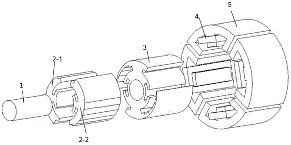
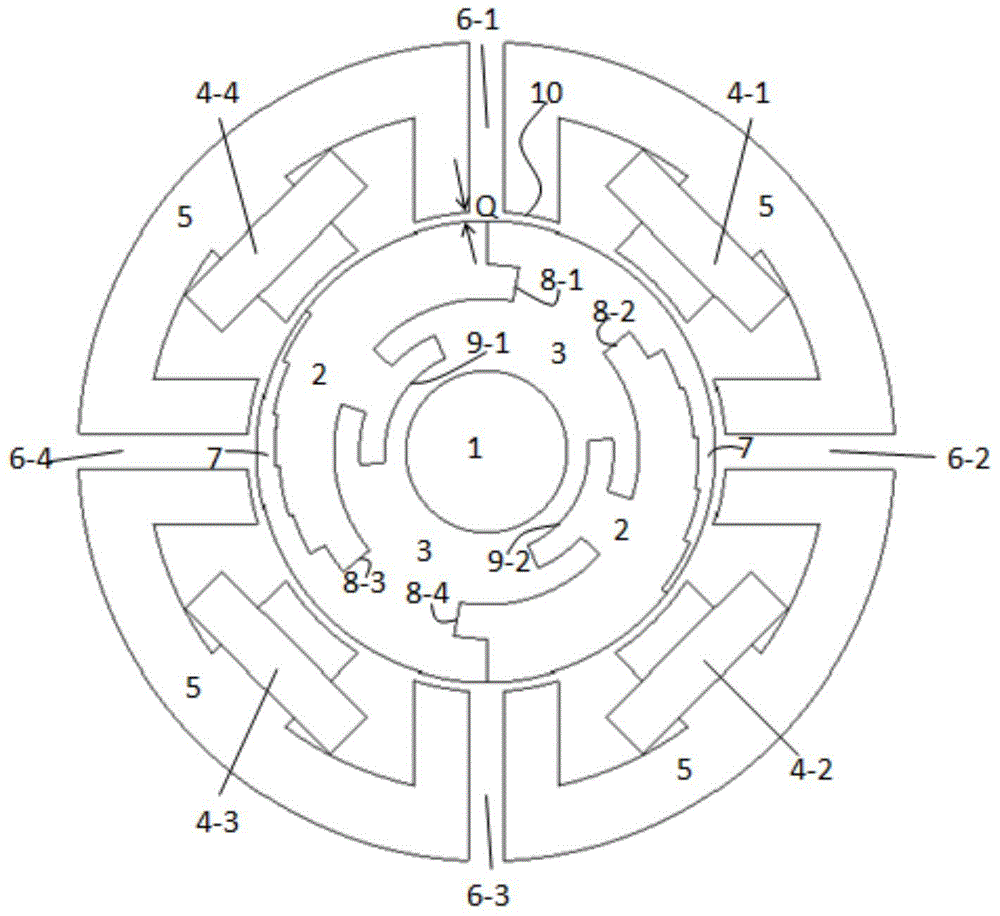
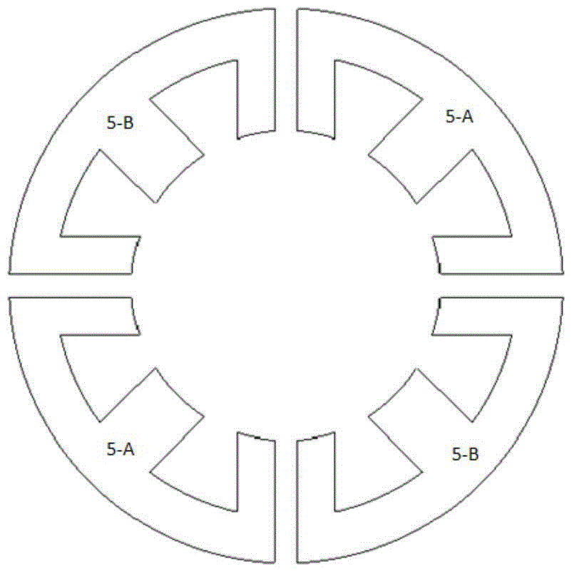
[0040] The stator-rotor segmented switched reluctance motor is a multi-phase motor. The number of poles of the motor stator (the number of E-shaped iron cores in the view of the end of the motor) is an even number, and the optimal number of phases is 2. The present invention intends to use 4 stators A two-phase switched reluctance motor with an E-shaped iron core structure and a rotor with two segmented magnetic core structures, that is, a 4-2 structure, will be described as an example. Such as figure 1 , 2 Shown is a two-phase stator E-type structure, stator and rotor segmented switched reluctance motor. The motor stator consists of an E-shaped iron core 5, coil windings 4-1 to 4-4 and magnetic isolation materials (located at the positions indicated by 6-1 to 6-4); figure 1 , 2 Shown is the structural diagram of a 4-pole stator-rotor segmented swit...


PUM


Abstract

The invention discloses a switch reluctance machine with a stator separated from a rotor. The switch reluctance machine comprises a rotor portion and a stator portion, wherein the rotor portion comprises a laminate iron core, a non-magnetic material frame and a rotating shaft, wherein the laminate iron core has an asymmetric structure and is inlaid in the non-magnetic material frame; the rotating shaft, the non-magnetic material frame and the laminate iron core are combined to form a cylindrical nonsalient pole structure; the stator portion comprises a plurality of independent detachable separate structures; the separate structures are the same; each separate structure comprises an E-shaped stator iron core; each E-shaped stator iron core consists of E-shaped magnetic materials which are laminated; an exciting winding is wound on a middle magnetic tooth of each E-shaped stator iron core; and the separate structures are isolated from one another via stator magnetism isolating materials. The magnetic flux path of the switch reluctance machine is short, and magnetic flux paths of different coil windings are independent from one another and are not stacked. The stator of the switch reluctance machine is detachable and is convenient to assemble.

Description

technical field [0001] The invention relates to a stator-rotor segmented switched reluctance motor. Background technique [0002] The switched reluctance motor follows the principle that the magnetic flux always closes along the path with the largest permeance, and the electromagnetic torque with reluctance properties is generated by the magnetic pull. Switched reluctance motors are simple and robust in construction. The stator coil is easy to embed, the end is firm, most of the heat loss is in the stator, and it is easy to cool; the rotor has no permanent magnet, which can have a higher maximum allowable temperature rise, no winding on the rotor, low cost, and the motor can rotate at high speed without Cause deformation, the moment of inertia of the rotor is small, easy to accelerate and decelerate; the torque direction of the switched reluctance motor has nothing to do with the direction of the phase current, as long as the on-off angle of the main switching device is con...

Claims


Application Information

Patent Timeline
Patent Type & Authority Applications(China)
IPC IPC(8): H02K19/00H02K1/14H02K1/24
Inventor 徐衍亮付东山
Owner SHANDONG UNIV
Why Eureka
Try Eureka