Optical burst transport network node time slot synchronization training method, node equipment and network

A node device, a technology for sending time slots, applied in the field of optical networks, can solve the problems of time slot synchronization method is not simple, difficult to build and adjust, high cost and so on

Active Publication Date: 2015-07-22
ZTE CORP
View PDF4 Cites 3 Cited by
  • Summary
  • Abstract
  • Description
  • Claims
  • Application Information

AI Technical Summary

Problems solved by technology

[0003] However, in the current OBTN technology, the use of FDL will bring high costs. At the same time, such a time slot synchronization method is not simple. It is necessary to make the fiber dista

Method used


Image

  • Optical burst transport network node time slot synchronization training method, node equipment and network
  • Optical burst transport network node time slot synchronization training method, node equipment and network
  • Optical burst transport network node time slot synchronization training method, node equipment and network

Examples


Embodiment Construction

[0054] The following will clearly and completely describe the technical solutions in the embodiments of the present invention with reference to the accompanying drawings in the embodiments of the present invention. Obviously, the described embodiments are only some, not all, embodiments of the present invention. Based on the embodiments of the present invention, all other embodiments obtained by persons of ordinary skill in the art without making creative efforts belong to the protection scope of the present invention.

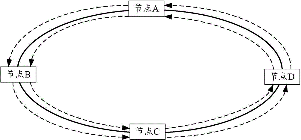
[0055] The OBTN separates the control channel from the data channel, and the data channel adopts the all-optical switching technology based on the data frame based on the OB as the switching unit. The control frame and the data frame in the control channel correspond one-to-one, and are also transmitted in the optical domain. Converted to electrical domain processing at nodes to receive and update corresponding control information. Therefore, it can become a g...


PUM


Abstract

Disclosed in the present invention are a time slot synchronization training method for an optical burst transport network node, node device and network. The method includes: a reference time delay between a receiving control frame and a receiving data frame is trained by the node, wherein the data frame and the control frame are in the same period; and time slots for sending adjacent data packets in the data frame are trained by the node.

Description

technical field [0001] The present invention relates to the technical field of optical networks, in particular to a training method, node equipment and network for node time slot synchronization of Optical Burst Transport Network (OBTN, Optical Burst Transport Network). Background technique [0002] OBTN is a granular optical transmission technology based on optical circuit switching (OCS, Optical Circuit Switching) and optical packet switching (OPS, Optical Packet Switching). Channels are separated from data channels. The data channel adopts the all-optical switching technology based on the data frame based on the optical burst (OB, Optical Burst) as the switching unit, while the control frame and the data frame in the control channel correspond one-to-one, and are also transmitted in the optical domain, but in the node is converted to circuit domain processing to receive and update corresponding control information. It is understandable that there can be more than one da...

Claims


Application Information

Patent Timeline
IPC IPC(8): H04J3/16H04Q11/00
CPCH04L12/4035H04L12/422H04J3/0652H04J3/0658H04J3/1652H04B10/275H04L7/0075H04Q11/0062H04Q11/0067H04Q2011/0079H04Q2011/0092
Inventor 卢苇尚迎春夏惠龙施社平王磊
Owner ZTE CORP
Why Eureka
Try Eureka