
Water-cooling double-row power tube electric vehicle controller

A technology for electric vehicle controllers and power tubes, which is applied in cooling/ventilation/heating transformation, casings/cabinets/drawer parts, etc. To avoid problems such as bad failure, to eliminate the hidden danger of overheating and burnout caused by poor heat conduction, to ensure timeliness and effectiveness, and to avoid excessive heat concentration

Inactive Publication Date: 2015-07-22
XUZHOU YUNYI TECH DEV
View PDF4 Cites 1 Cited by
  • Summary
  • Abstract
  • Description
  • Claims
  • Application Information

AI Technical Summary

Problems solved by technology

[0003] The power tubes are distributed in a single row, and the heat generated by the power tubes is too concentrated during operation. In addition, the heat conduction path is too long when the heat is transmitted to the aluminum heat dissipation shell through the heat conduction aluminum strip, and the heat dissipation effect is poor. The power tube is burnt out and fails, and the controller function is lost
Affected by the quality of the thread on the heat-conducting aluminum strip, the locking force of individual power tubes and heat-conducting aluminum strips is small when the screws are locked or the wires are slippery, resulting in poor fit of some power tubes, and the heat of the power tubes cannot be effectively conducted out, causing some The power is burned out and the controller function is lost

Method used


Image

  • Water-cooling double-row power tube electric vehicle controller
  • Water-cooling double-row power tube electric vehicle controller
  • Water-cooling double-row power tube electric vehicle controller

Examples


Embodiment Construction

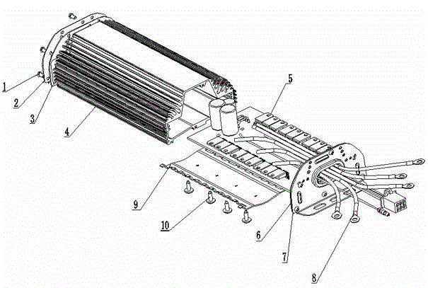
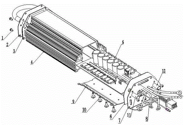
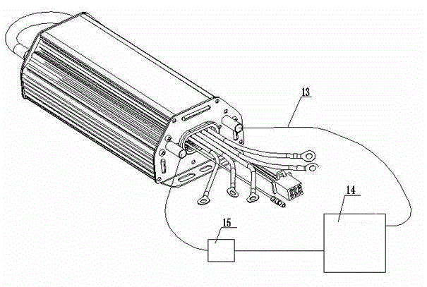
[0018] Such as image 3 , Figure 4 Shown: The present invention includes screws (1), rear baffle (2), rear gasket (3), shell (4), power tube (5), front gasket (6), front baffle (7) , Functional wiring harness (8), spring leaf (9), compression screw (10), water inlet pipe (11), water outlet pipe (12), rubber water pipe (13. The shell (4) is hollow and the bottom is Arch shape, two cooling water pipes are installed on both sides of the shell (4), and there are also eighteen power tubes (5) and functional wiring harness (8), power cords and crimping power welded on the circuit board. The spring piece (9) of the tube. At both ends of the housing (4) are provided with a front baffle (7) and a rear baffle (2) with a water inlet pipe (11) and a water outlet pipe (12), and the front baffle ( 7) A front gasket (6) is arranged between the housing (4), a rear gasket (3) is arranged between the rear baffle (2) and the housing (4), and the crimping screw (10) head The part has a step and...


PUM


Abstract

The invention discloses a water-cooling double-row power tube electric vehicle controller. The water-cooling double-row power tube electric vehicle controller comprises a hollow shell, a front sealing pad, a front stop plate, a rear sealing pad, a rear stop plate, screws, compression joint screws, a spring piece and eighteen power tubes welded on a circuit board. The water-cooling double-row power tube electric vehicle controller is characterized in that the bottom of the hollow shell is arched, two cooling water tubes are mounted on two sides in the shell, and the eighteen power tubes welded on the circuit board, functional wiring harnesses, a power line and the spring piece for compression joint of the power tubes are arranged in the shell. The front stop plate and the rear stop plate are arranged at two ends of the shell, and each of the front stop plate and the rear stop plate is provided with a water inlet tube and a water outlet tube. The water inlet tube and the water outlet tube of the front stop plate are connected with an external water pump and an external water tank through rubber water tubes to form a water circulation channel. The water-cooling double-row power tube electric vehicle controller has the advantages that close fitting between the power tubes and the inner surface of the hollow shell is guaranteed, and a heat conduction path is shortest; circular cooling water can carry away heat generated by the power tubes timely, and heat conduction timeliness and effectiveness are guaranteed.

Description

Technical field [0001] The invention relates to an electric vehicle controller, in particular to a water-cooled double-row power tube electric vehicle controller. Background technique [0002] With the development of society and the continuous increase of fuel vehicles, the problems of human beings facing the shortage of natural resources such as petroleum fuels and fuel emissions leading to global warming have become increasingly prominent. Therefore, under this background, hybrid or pure power transportation vehicles have gradually entered people's lives, and electric vehicles have emerged. The controller is the core component of the electric vehicle. It controls the electric current of the electric motor to ensure the power required for the vehicle to run, and plays a vital role in ensuring the normal running and safety of the vehicle. In the state of the art, the double-row power tube electric vehicle controller mostly has a hollow shell in the middle, and the front baffle a...

Claims


Application Information

Patent Timeline
Patent Type & Authority Applications(China)
IPC IPC(8): H05K5/02H05K7/20
Inventor 杜淑梅
Owner XUZHOU YUNYI TECH DEV
Learn More