Filter Element

A filter element, flat filter technology, applied in the direction of membrane filter, dispersed particle filtration, separation method, etc., can solve the problems of poor separation effect, small dust storage capacity, high flow resistance, etc., to achieve small pressure loss, dust storage The effect of enhanced capacity and compact construction method

Inactive Publication Date: 2015-07-29
CARL FREUDENBERG KG
View PDF7 Cites 4 Cited by
  • Summary
  • Abstract
  • Description
  • Claims
  • Application Information

AI Technical Summary

Problems solved by technology

[0004] Furthermore, inertial separators known from the prior art frequently exhibit high flow resistance, poor separation effect and small dust storage capacity

Method used


Image

  • Filter Element
  • Filter Element

Examples


Embodiment Construction

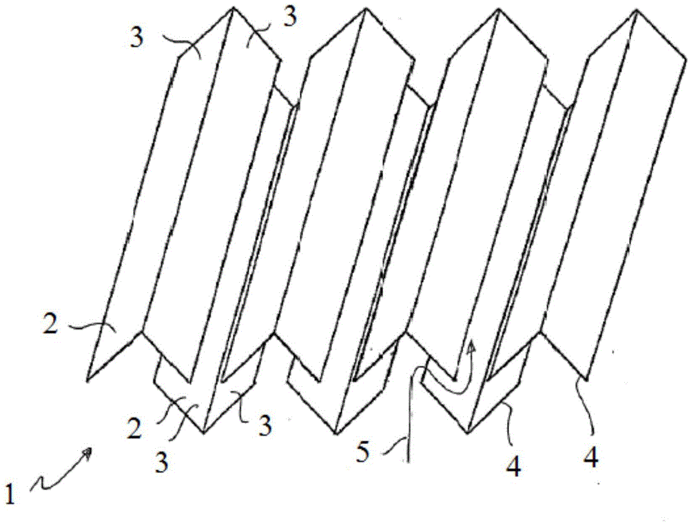
[0019] figure 1 Shown is a filter element 1 designed as an inertial separator, ie with a device 2 that separates particles by deflection of a flow medium. Device 2 has a nonwoven.

[0020] The device 2 is designed as a folding wall 3 which is produced from or has a nonwoven.

[0021] The filter element 1 has a plurality of V-shaped or saddle-shaped folded wall pairs 4 , wherein each two folded wall pairs 4 are spaced apart from each other, arranged opposite each other and offset relative to each other, so that at least one flow channel 5 is formed between these folded wall pairs . The flow channels 5 are schematically indicated by arrows.

[0022] The folded wall pairs 4 each span two planes, wherein the planes are spaced from one another, and the folded wall pairs 4 are likewise spaced apart from one another in the planes.

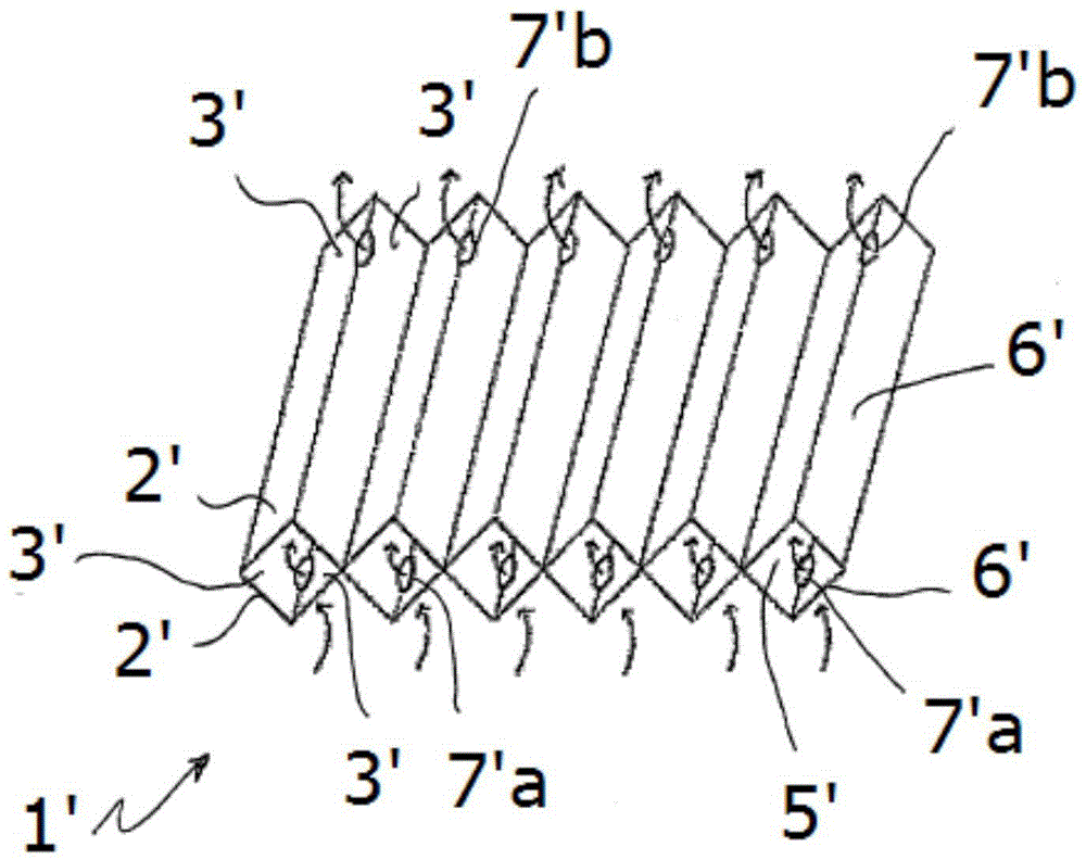
[0023] figure 2 Shown is a filter element 1 ′ designed as an inertial separator, ie with a device 2 ′, which separates particles by deflection of t...


PUM


Abstract

In respect of the object of specifying a filter element which can be used as an inertial separator and, while being of compact construction, can be used in small installation spaces, said filter element displaying a low level of flow resistance, the highest possible dust-holding capacity and the best possible separating-off action, a filter element which is configured in the form of an inertial separator, that is to say has means which separate off particles by deflection of a flow medium, is characterized in that the means comprise, or have, nonwoven fabric.

Description

technical field [0001] The invention relates to a filter element designed as an inertial separator. Background technique [0002] Document EP 1 262 223 A1 discloses an oil mist separator. Larger particles are first separated by this inertial separator. Furthermore, solutions for separating liquid aerosols are known from the prior art. However, this known inertial separator does not allow a compact construction suitable for small installation spaces. [0003] Against this background, there is a need for an inertial separator which can be used in a smaller construction space. Especially in motor vehicles there is less installation space. [0004] Furthermore, the inertial separators known from the prior art frequently exhibit high flow resistance, poor separation effect and low dust storage capacity. Contents of the invention [0005] It is therefore the object of the present invention to provide a filter element which can be used as an inertial separator, which is comp...

Claims


Application Information

Patent Timeline
Patent Type & Authority Applications(China)
IPC IPC(8): B01D50/00
CPCB01D46/521B01D46/002B01D46/0027B01D2273/10B01D46/58B01D50/20
Inventor A·拉扎列维奇V·布劳恩灵R·陆瑟尔
Owner CARL FREUDENBERG KG
Why Eureka
Try Eureka