Supercharge Your Innovation With Domain-Expert AI Agents!

Impeller fixing structure and fixing method of a miniature rotary mechanical pump

A technology of rotating machinery and fixed structure, applied in mechanical equipment, components of pumping devices for elastic fluids, pumps, etc., can solve the problems of increased assembly difficulty, increased machining accuracy, large assembly stress, etc., and achieves axial positioning. The effect of easy adjustment, small change of parts and high fixing strength

Active Publication Date: 2017-12-22
HUAZHONG UNIV OF SCI & TECH
View PDF11 Cites 0 Cited by
  • Summary
  • Abstract
  • Description
  • Claims
  • Application Information

AI Technical Summary

Problems solved by technology

This process also has limitations: the interference of parts in the matching of micro-workpieces is generally on the order of 0.01mm. If the interference is too small, it will easily cause the load to fall off, and if it is too large, it may cause excessive assembly stress and damage the workpiece.
However, there are two main constraints in this invention: one is that the radial size of standard miniature bearings is constrained, and the diameter of the inner ring cannot be reduced indefinitely due to the limitation of the processing technology level; second, the additional miniature bearings increase the manufacturing cost, and usually Yes, the smaller the size of the miniature bearing, the higher the manufacturing cost
[0006] In summary, the application of the common shaft end fixing methods mentioned above to miniature shaft end fixing will result in complex structures, improved machining accuracy, increased assembly difficulty, and low structural reliability.

Method used


Image

  • Impeller fixing structure and fixing method of a miniature rotary mechanical pump
  • Impeller fixing structure and fixing method of a miniature rotary mechanical pump
  • Impeller fixing structure and fixing method of a miniature rotary mechanical pump

Examples


Embodiment Construction

[0022] The present invention will be described in further detail below in conjunction with the accompanying drawings.

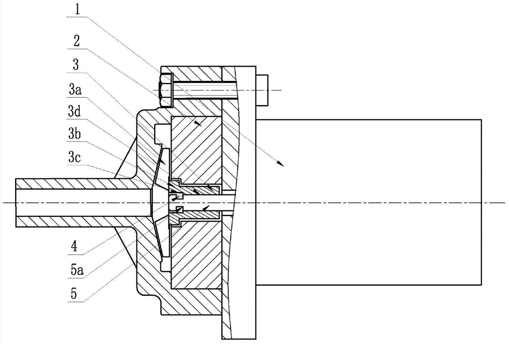
[0023] Such as figure 1 As shown, the impeller 3 is fixed on the motor shaft 5, and the blades 3a on the impeller 3 are placed in the pressurized water chamber. One end surface of the front cover 2 is in close contact with the motor 1 and both are concentric. The output shaft section of the motor shaft 5 is provided with two square straight grooves 5a, and the opening direction of the square straight grooves 5a is perpendicular to the axial direction of the motor. One end of the impeller hub 3b is provided with a packing stepped hole 3c, and the diameter of the stepped hole is slightly larger than that of the shaft hole.

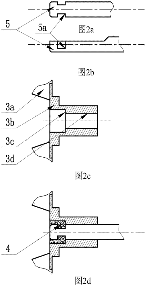
[0024] figure 2 The fixing structure of the present invention is described in more detail. Such as figure 2 The output shaft section of the motor shaft 5 shown in b is processed with a D-shaped flat part to cooperate with the D-shape...


PUM


Abstract

The invention discloses an impeller fixing method for a micro-rotating mechanical pump. The impeller fixing method for the micro-rotating mechanical pump is mainly used for fixing micro-rotating mechanical pumps and other micro-shaft ends. The micro-rotating mechanical pump mainly comprises an impeller, a motor shaft and filler. The impeller comprises blades and a hub fixed at the motor shaft end, a filler ladder hole is opened in one end of the impeller hub, a channel is opened in the shaft section of the motor shaft inserted in one side of the impeller hub, and the open direction of the channel is vertical to the axial direction. After the motor shaft passes the impeller hub, the motor shaft channel completely locates in the filler ladder hole in one end of the hub, and the filler is filled and cured in a space surrounded by the filler ladder hole and channel so as to form a hub-motor shaft occlusion structure to fix the impeller on the motor shaft in the small space. Compared with a simple hub-motor shaft splicing technique, the hub-motor shaft occlusion technique structure has a higher fixing intensity.

Description

technical field [0001] The invention relates to a method for fixing a shaft end of a miniature rotary machine, in particular to a method for fixing an impeller of a miniature rotary machine pump. Background technique [0002] With the development of microchannel liquid cooling technology, microfluidic technology, and special pumping technology, micromechanical pumps have a wide range of application space and prospects as the power source of their fluid systems. Among them, the micro-impeller is the hydraulic component of the micro-mechanical pump, which converts the shaft work output by the motor into the kinetic energy and pressure energy of the working fluid. The fixed structure of the shaft end is related to the complexity of the installation process and the reliability of the whole pump operation. [0003] There are many particularities in the micro-shaft end fixing structure. Taking the micro-mechanical pump described in this patent as an example, the diameter of the mo...

Claims


Application Information

Patent Timeline
Patent Type & Authority Patents(China)
IPC IPC(8): F04D29/20
CPCF04D29/20
Inventor 罗小兵段斌罗明清郭庭辉
Owner HUAZHONG UNIV OF SCI & TECH
Features
  • R&D
  • Intellectual Property
  • Life Sciences
  • Materials
  • Tech Scout
  • Unparalleled Data Quality
  • Higher Quality Content
  • 60% Fewer Hallucinations
Learn More