Centrifugal type three-gear automatic speed changing system for electric car

An automatic speed change, centrifugal technology, applied in the direction of transmission, gear transmission, belt/chain/gear, etc., can solve the problems of unfavorable promotion and later use, complex system, high cost, widen the range of transmission ratio and system stability. The effect of high performance and reduced performance requirements

Inactive Publication Date: 2015-07-29
NANNING UNIV
View PDF6 Cites 8 Cited by
  • Summary
  • Abstract
  • Description
  • Claims
  • Application Information

AI Technical Summary

Problems solved by technology

However, most of the automatic transmissions of electric vehicles currently adopt hydraulic control or electronic control, and are also sepa

Method used


Image

  • Centrifugal type three-gear automatic speed changing system for electric car
  • Centrifugal type three-gear automatic speed changing system for electric car
  • Centrifugal type three-gear automatic speed changing system for electric car

Examples


Embodiment 1

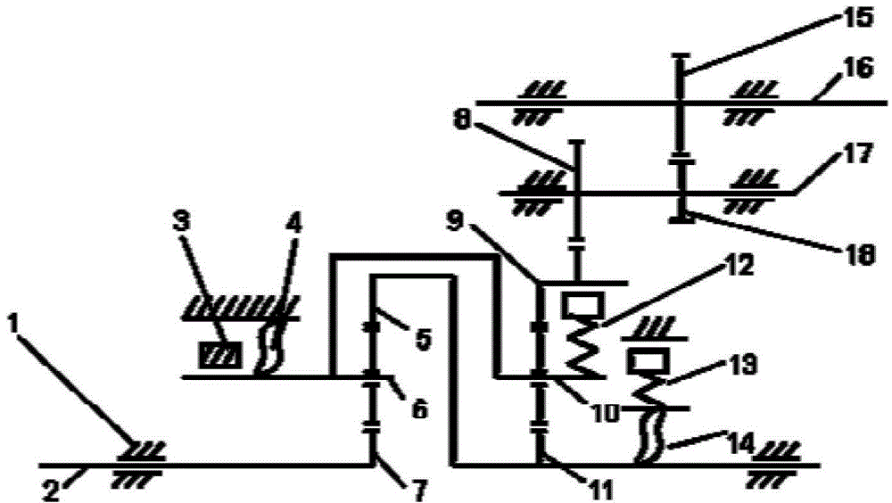
[0050] figure 1 An implementation form according to the present invention is shown, which includes: the final drive and the transmission, both of which are integrated and wrapped by the casing 1; the final drive can be connected before the transmission or after the transmission.

[0051] Wherein, the transmission includes:

[0052] Transmission mechanism, which is a double-row planetary system composed of input shaft 2, front row sun gear 7, front row planet carrier 6, front row ring gear 5, rear row planet carrier 10, rear row sun gear 11 and rear row ring gear 9 A gear mechanism, wherein the front row sun gear 7 is connected to the input shaft 2, the front row planet carrier 6 is connected to the rear row planet carrier 10, and the front row ring gear 5 is connected to the rear row sun gear 11; and

[0053] Regulates the shift mechanism, which includes:

[0054] F1 one-way overrunning clutch 4, which is arranged between the housing 1 and the front row planet carrier 6 to p...

Embodiment 2

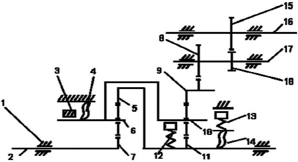
[0074] figure 2 Another implementation form of the present invention is shown, the electric vehicle centrifugal three-speed automatic transmission of this figure and the centrifugal clutch 12 in the final drive are located between the rear row planet carrier 10 and the rear row sun gear 11; its Effect is, when being in the forward third gear, the centrifugal clutch 12 works, and the rear planetary carrier 10 is connected with the rear sun gear 11, making the front and rear planetary gears as a whole.

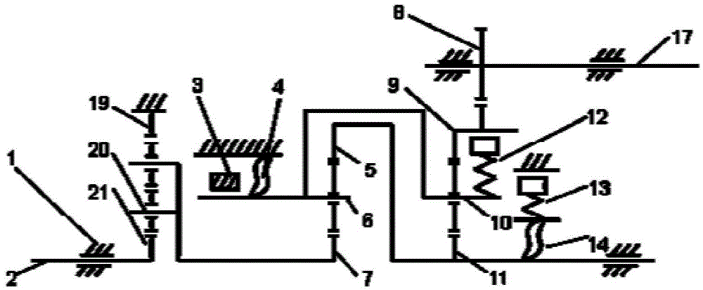
[0075] Such as image 3 and Figure 4 Different embodiments of the final drive are shown, including:

[0076] a single-row double-stage planetary gear set or a single-row single-stage gear set, which is connected between the input shaft 2 and the front sun gear 7;

[0077] The intermediate shaft 17 is connected to the rear ring gear 9 and outputs power.

Embodiment approach

[0079] Such as image 3 An embodiment of the final drive is shown, and the single-row double-stage planetary gear set includes:

[0080] a sun gear 21, which is connected to the input shaft 2;

[0081] a double planetary gear, which is arranged on the planetary carrier 20 and meshes with the sun gear 21, so as to rotate around the sun gear 21 while itself rotating;

[0082] Planet carrier 20, which is connected to the front sun gear 7, and reversely decelerates the power input to the front sun gear 7;

[0083] The ring gear 19 is fixed on the housing 1 and meshes with the double planetary gears.

[0084] The electric vehicle centrifugal three-speed automatic transmission of this example and the final drive in the final drive are located before the input shaft, including a single-row two-stage planetary gear set, ring gear 19, planet carrier 20, sun gear 21, wherein the ring gear 19 is connected with the housing, the input shaft is connected with the sun gear 21, and the pla...


PUM


Abstract

The invention discloses a centrifugal type three-gear automatic speed changing system for an electric car. The centrifugal type three-gear automatic speed changing system comprises a main speed reducer and a speed changer; the speed changer is provided with an F1 one-way overrunning clutch, a centrifugal clutch, a belt brake, a centrifugal brake and an F2 one-way overrunning clutch which can respectively and automatically control a front-row gear ring, a front-row planet carrier, a front-row sun wheel, a rear-row gear ring, a rear-row planet carrier and a rear-row sun wheel in different gears. Thus, automatic gear shifting of the electric car is achieved, a complex electric control module and a complex hydraulic system are removed, the endurance mileage of the electric car is improved, and the service life of batteries is prolonged. Meanwhile, the main speed reducer and the speed changer are integrally connected, and the speed ratio range is improved. Furthermore, the speed changing system is smooth in gear shifting, compact in structure, high in reliability, light in weight, small in size, low in cost and high in transmitting efficiency.

Description

technical field [0001] The invention belongs to the technical field of electric vehicle transmission, in particular to a centrifugal three-speed automatic transmission system for electric vehicles. Background technique [0002] At present, short driving range and insufficient acceleration performance at medium and high speeds are one of the important reasons restricting the popularization of electric vehicles. Through the improvement of the transmission system, the weight of the powertrain can be reduced, the requirement for the torque of the motor can be reduced, and the mileage and performance of the vehicle can be improved. The electric vehicle adopts a two-speed or multi-speed automatic transmission, which can improve the vehicle's gradeability, acceleration performance, and maximum speed, reduce the use time of the motor at peak load, and increase the mileage. However, most of the current electric vehicle automatic transmissions adopt hydraulic control or electronic co...

Claims


Application Information

Patent Timeline
IPC IPC(8): F16H3/66
CPCF16H3/66
Inventor 范毅禤旭旸邓汝奎梁巍陆海
Owner NANNING UNIV
Why Eureka
Try Eureka