
High-precision cable force testing instrument of magnetic permeability cable and test method thereof

A tester, high-precision technology, applied in force/torque/work measuring instruments, instruments, measuring devices, etc., can solve the problems of complex calculation steps, 3rd harmonic interference, data processing difficulty, etc., to achieve a wide range of applications, Good durability and accurate measurement

Inactive Publication Date: 2015-07-29
SHANGHAI TONGLEI CIVIL ENG TECH +1
View PDF8 Cites 2 Cited by
  • Summary
  • Abstract
  • Description
  • Claims
  • Application Information

AI Technical Summary

Problems solved by technology

[0004] This cable force test method has obvious disadvantages:
[0005] 1) The boundary conditions need to be clear: There are generally two forms of cables in practical applications: one cable body is fixed at both ends on a rigid structure, such as cables in tied arch bridges and cable-stayed bridges, and its two ends are fixed on bridge decks and steel structures. On the arch ring or on the bridge deck and cable tower, this kind of cable body can be tested by the vibration method; the other end of the cable body is not fixed on a rigid structure, such as space structure systems such as space grids, cable net curtain walls, and string beams , for this structural system, the boundary conditions at both ends of the cable body are uncertain, and the cable force cannot be calculated by the vibration method
[0006] 2) The vibration method calculates the frequency through the acceleration, and then calculates the cable force through the frequency. The calculation steps are complicated, and it is easy to be interfered by the third harmonic in the process of calculating the frequency through the acceleration, so there is a certain difficulty in data processing.
[0007] Therefore, the traditional cable force test method has its fatal limitations

Method used


Image

  • High-precision cable force testing instrument of magnetic permeability cable and test method thereof
  • High-precision cable force testing instrument of magnetic permeability cable and test method thereof

Examples


Embodiment Construction

[0033] Embodiments of the present invention will be further described below in conjunction with the accompanying drawings.

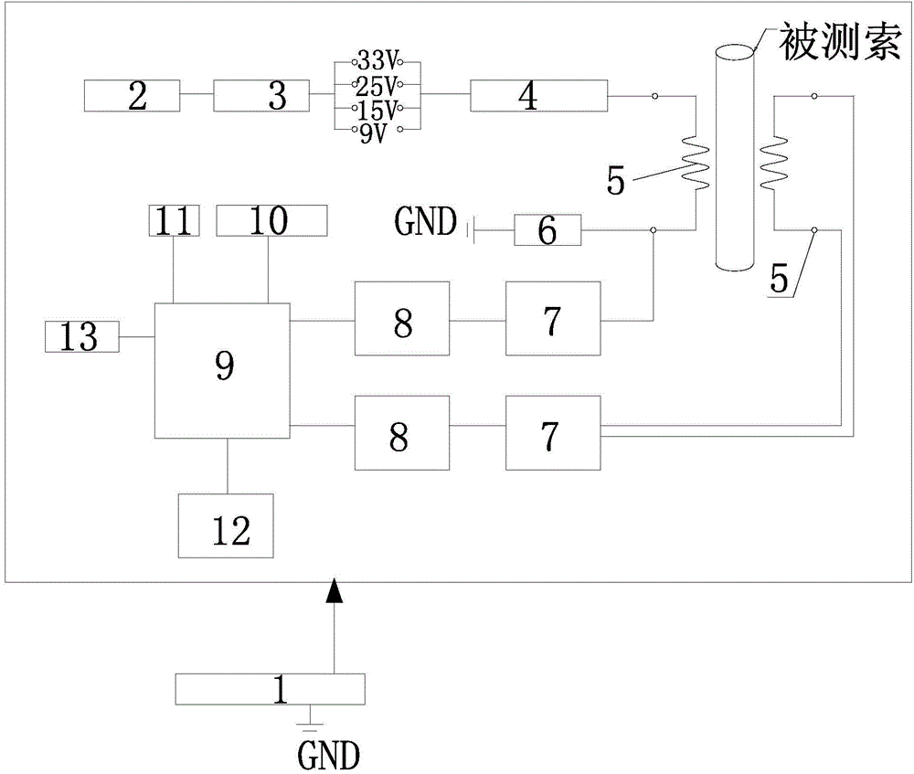
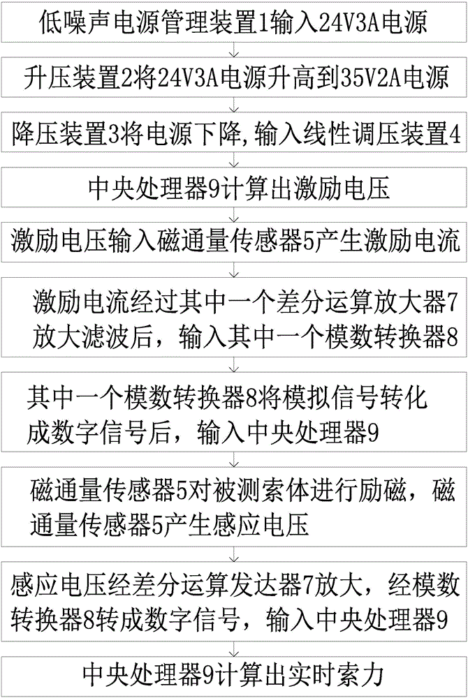
[0034] Please see attached figure 1 As shown, a high-precision cable force tester for magnetic cables includes a low-noise power management device 1, a voltage booster 2, a voltage drop device 3, a linear voltage regulator 4, a magnetic flux sensor 5, a MOS tube 6, two Differential operational amplifier 7, two analog-to-digital converters 8, central processing unit 9, 485 isolation circuit 10, network card 11 and SD card memory 12; one end of the described step-up device 2 and one end of the described step-down device 3 connected, the other end of the pressure reducing device 3 is connected to one end of the linear voltage regulating device 4; the magnetic flux sensor 5 is in a ring structure, and the magnetic flux sensor 5 is sleeved on the cable body to be tested, The two ends of one side of the magnetic flux sensor 5 are respectively connected with t...


PUM


Abstract

The invention discloses a high-precision cable force testing instrument of a magnetic permeability cable and a test method thereof. The testing instrument comprises a low-noise power source management device, a boost device, a voltage drop device, a linear voltage adjustment device, a magnetic flux sensor, an MOS (Metal Oxide Semiconductor) tube, two differential operational amplifiers, two analog-digital converters, a central processor, a 485 isolation circuit, a network card and a SD (Security Digital) memory card storage. A cable body to be tested does not need clear boundary conditions, nearly all the magnetic permeability cable can be used, and the application range is particularly wide; the durability of each element is good, and long-term field application can be realized; 18-bit high-speed AD is adopted, so the precision is high and the measurement is accurate; an industrial grade magnetic coupling isolation 485 special chip is adopted, isolation voltage reaches 5000 V, and 15kV electrostatic interference can be resisted; a 10 / 100Mb / s self-adaption industrial grade network card chip is adopted, and error-free transmission can reach 150 m.

Description

technical field [0001] The invention relates to a real-time cable force monitoring device for steel rods, steel tie rods and steel cables, in particular to a high-precision cable force tester for magnetically conductive cables and a test method thereof. Background technique [0002] With the continuous development of various construction engineering fields such as buildings, roads, bridges, and water conservancy, engineering safety has become the focus and attention of future development. Safety detection and monitoring and the early warning information provided are undoubtedly the top priority of future development. [0003] The traditional cable force test uses the vibration method, that is, an acceleration sensor is installed at the 1 / 2 length point of the cable fixed at both ends. The cable vibrates under natural excitation such as wind load. Since the two ends of the cable are fixed, the first-order frequency picked up by the acceleration sensor is equal to the natur...

Claims


Application Information

Patent Timeline
IPC IPC(8): G01L5/00
Inventor 张少荃张韵秋
Owner SHANGHAI TONGLEI CIVIL ENG TECH
Learn More