
Grinding device

A technology of grinding discs and disc grinding machines, which is applied in the preparation of test samples, etc., can solve problems such as hot hands cannot be handled, grinding discs are broken, silicon wafers are heated, etc., and it is suitable for popularization and application, realizing automation and preventing fragmentation Effect

Inactive Publication Date: 2015-07-29
CSI CELLS CO LTD +1
View PDF8 Cites 1 Cited by
  • Summary
  • Abstract
  • Description
  • Claims
  • Application Information

AI Technical Summary

Problems solved by technology

However, this method has the following problems: (1) A large amount of heat will be generated during grinding, which will cause the silicon wafer to heat up, causing it to be hot and difficult to handle; Grinding operations at special angles, and the thickness of the grinding disc is uncontrollable, and the working surface of the silicon wafer is uneven
[0004] In response to the above problems, on-site operators used some clamping tools, such as clips. Although the first problem above was solved, the second problem still could not be solved
In addition, it is difficult to control the force of the clamping tool to hold the sample, and it is also difficult to control the force of the sample contacting the grinding wheel during grinding, which will also cause the problem of grinding disc fragmentation
[0005] Therefore, it is obviously of positive practical significance to develop a grinding device to achieve precise grinding at any angle and effectively prevent the problem of grinding disc fragmentation

Method used


Image

  • Grinding device
  • Grinding device
  • Grinding device

Examples


Embodiment 1

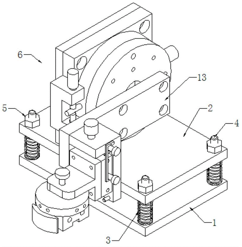
[0037] see Figure 1~5 As shown, a grinding device includes a frame and a grinding machine located on the frame, and also includes a clamping mechanism 6,

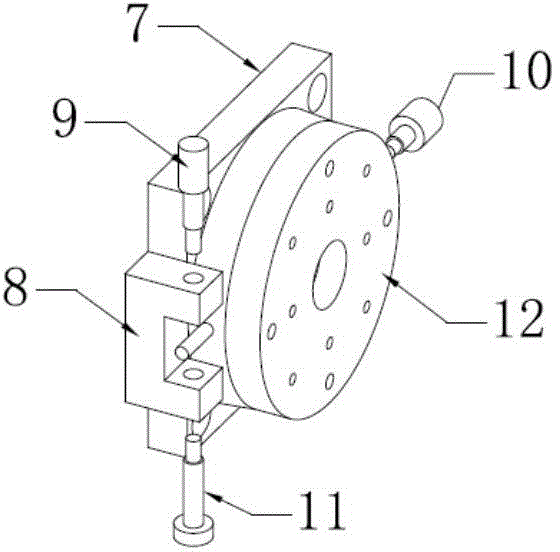
[0038] The clamping mechanism includes a liftable platform, and the surface of the liftable platform is fixed with a rotating pillow block, and the rotating surface of the rotating sliding table of the rotating pillow block is located in a vertical plane, so that the rotating sliding table has a rotation relative to the lifting platform. degrees of freedom;

[0039] A connection plate 13 is fixed on the rotary slide of the rotary pillow block, one end of the connection plate is fixedly connected to the rotary slide, and the other end is fixed with an up and down fine-tuning mechanism;

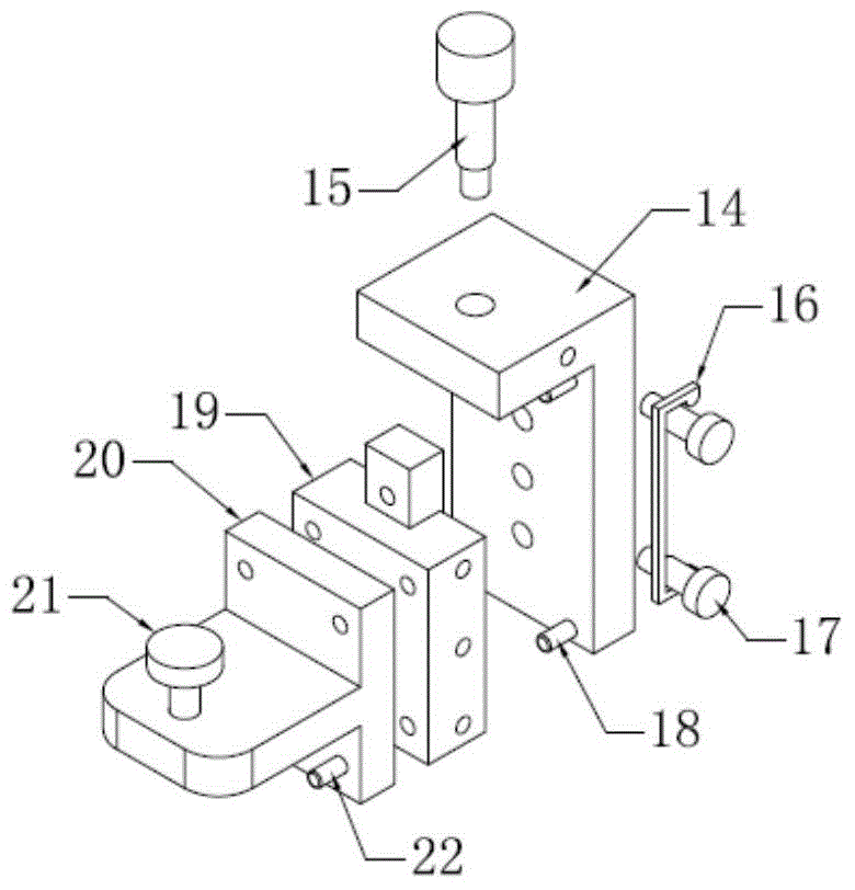
[0040] The up and down fine-tuning mechanism includes a fixed plate 14, a precision linear guide rail 19 and a locking block 20, one side of the fixed plate is fixedly connected with the connecting plate, and a precision linear guide rail ...


PUM


Abstract

The invention discloses a grinding device which comprises a stander and a grinding machine arranged on the stander, and further comprises a clamping mechanism, wherein the clamping mechanism comprises a lifting platform; a rotating shaft table is fixedly arranged on the surface of the lifting platform; the rotating surface of a rotating sliding table of the rotating shaft table is positioned in a vertical plane, so that the rotating sliding table has a rotating degree of freedom relative to the lifting platform; the grinding device further comprises a sample table; the sample table and a locking block form a detachable connection structure. By arrangement of the lifting platform, adjustment of the up-and-down position of a sample is realized, and by arrangement of the rotating shaft table, adjustment of the circumferential rotating position of the sample is realized, so that precise grinding of any angle is realized.

Description

technical field [0001] The invention relates to a grinding device, which is especially suitable for thin samples such as silicon chips and battery chips. Background technique [0002] At present, in the photovoltaic industry, in order to test samples (such as silicon wafers, cells, etc.), scanning electron microscopes are generally used for surface morphology observation and fracture failure analysis. Before performing the above-mentioned detection, it is generally necessary to grind the sample to reveal the place where the sample needs to be observed and analyzed. [0003] In the prior art, an ordinary grinding machine is generally used for grinding operations, that is, the silicon wafer (or cell) is held by hand and ground against a grinding wheel. However, this method has the following problems: (1) A large amount of heat will be generated during grinding, which will cause the silicon wafer to heat up, causing it to be hot and difficult to handle; Special angle grinding...

Claims


Application Information

Patent Timeline
Patent Type & Authority Applications(China)
IPC IPC(8): G01N1/32
Inventor 孙祥王栩生邢国强
Owner CSI CELLS CO LTD
Learn More