Permanent magnet speed regulator

A permanent magnet governor and permanent magnet technology, applied in the direction of electrical components, electromechanical devices, electromechanical transmission devices, etc., can solve the problems of difficult application in places with limited space, and achieve easy adjustment of magnetic flux, simple structure, axial The effect of shrinking space

Active Publication Date: 2015-07-29
西安正奇能源科技有限公司
View PDF6 Cites 11 Cited by
  • Summary
  • Abstract
  • Description
  • Claims
  • Application Information

AI Technical Summary

Problems solved by technology

It is difficult to apply in some places with limited space

Method used


Image

  • Permanent magnet speed regulator
  • Permanent magnet speed regulator
  • Permanent magnet speed regulator

Examples


Embodiment 1

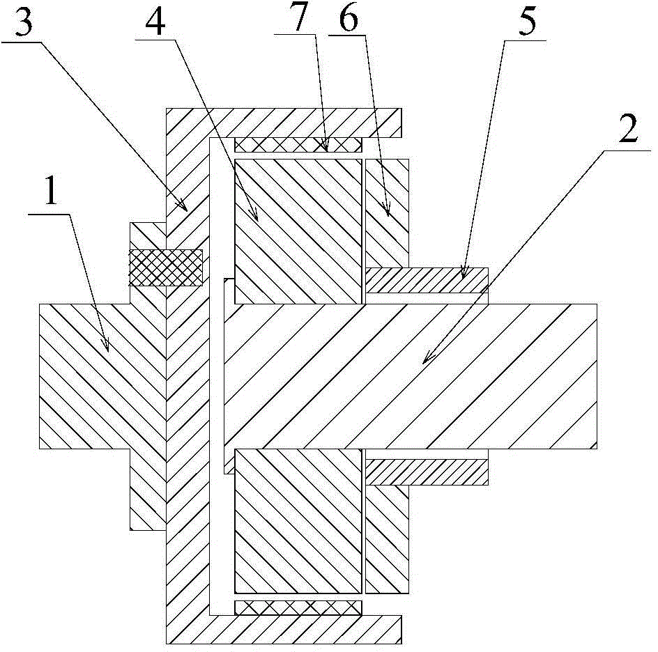
[0025] like Figure 1~2 As shown, a permanent magnet governor includes a cylindrical conductor rotor 3, a permanent magnet rotor 4 and a magnetic yoke 6, the conductor rotor 3, the permanent magnet rotor 4 and the magnetic yoke 6 are arranged coaxially, and the permanent magnet rotor 4 Located in the inner cavity of the conductor rotor 3, a radial air gap is set between the permanent magnet rotor 4 and the conductor rotor 3, the magnetic yoke 6 is located on the screw sleeve 5 outside the permanent magnet rotor 4, and the screw sleeve 5 is connected to the outer base The seat or bracket is connected and fixed, the magnetic yoke 6 can move axially on the lead screw sleeve 5, and the adjustment of the radial air gap magnetic field intensity is realized by adjusting the distance between the magnetic yoke 6 and the permanent magnet rotor 4 . The magnetic yoke 6 refers to the soft magnetic material that does not produce a magnetic field (line of force) itself, and only transmits th...

Embodiment 2

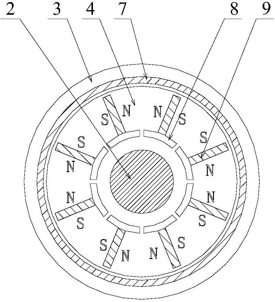
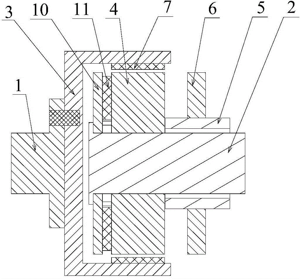
[0033] like Figure 3-4As shown, in order to further increase the permanent magnet flux provided by the permanent magnet rotor 4 , this embodiment is improved on the basis of the first embodiment above. This embodiment also includes a magnetism gathering structure coaxial with the permanent magnet rotor 4, the magnetism gathering structure is arranged inside the permanent magnet rotor 4, the magnetism gathering structure includes a second permanent magnet magnet steel 11 and an end magnetism gathering permeable disk 10, the first Two permanent magnets 11 are located between the permanent magnet rotor 4 and the end magnetically permeable disk 10, the second permanent magnets 11 correspond to the first permanent magnets 9 one by one, and the second permanent magnets 11 correspond to the corresponding The magnetic poles of the first permanent magnet steel 9 are the same. The magnetically permeable disk 10 at the end can protect the second permanent magnetic steel 11 and form a c...


PUM


Abstract

The invention discloses a permanent magnet speed regulator. The permanent magnet speed regulator comprises a barrel-shaped conductor rotor, a permanent magnet rotor and a magnetic conductive yoke which are coaxially arranged, wherein the permanent magnet rotor is positioned in an inner cavity of the conductor rotor; a radial air gap is formed between the permanent magnet rotor and the conductor rotor; the magnetic conductive yoke is positioned at the outer side of the permanent magnet rotor and can axially move; the magnetic field strength of the radial air gap can be adjusted by adjusting the distance from the magnetic conductive yoke to the permanent magnet rotor. According to the permanent magnet speed regulator, the magnetic conductive yoke can be moved to adjust the torque and the rotating speed; the required axial space is greatly reduced by being compared with the traditional barrel-shaped permanent magnet speed regulator; in addition, the magnetic flux of the radial air gap can be adjusted through the magnetic conductive yoke with small effect force; the problems of large axial space, complex speed regulating mechanism and large acting force of the traditional barrel-shaped permanent magnet speed regulator can be solved.

Description

technical field [0001] The invention relates to a driving speed regulating device, in particular to a permanent magnet speed regulating device. Background technique [0002] In large-scale mining, petrochemical, electric power and metallurgy industries, due to the needs of energy saving and environmental protection, the application of permanent magnet speed control devices is becoming more and more widespread. The permanent magnet speed control device can adapt to various harsh environments, including places with large grid voltage fluctuations, serious harmonics, flammable, explosive, humid, dusty, etc., and can adjust the speed of the load online to meet the actual operation needs of the system and realize speed regulation Energy saving, the energy saving rate is 10% to 65%. [0003] The existing permanent magnet governor mainly includes cylindrical permanent magnet governor and disc permanent magnet governor. To change the effective part of the coupling between the perm...

Claims


Application Information

Patent Timeline
Patent Type & Authority Applications(China)
IPC IPC(8): H02K16/02H02K51/00
Inventor 张胜川边建华
Owner 西安正奇能源科技有限公司
Why Eureka
Try Eureka