DC deviation correcting method and device

A technology of DC offset and correction method, which is applied in the field of radio frequency communication, can solve the problems of narrow application range, lower dynamic range of amplifier and ADC, and lack of real-time performance, so as to achieve good real-time performance

Active Publication Date: 2015-07-29
SOUTH CHINA UNIV OF TECH
View PDF4 Cites 13 Cited by
  • Summary
  • Abstract
  • Description
  • Claims
  • Application Information

AI Technical Summary

Problems solved by technology

Its advantage is that it can automatically adjust the size of the DC offset calibration value according to the change of some circuit parameters (such as receiving gain); its disadvantages are: a. It cannot be changed according to other circuit parameters (such as the corresponding response caused by the change of the carrier frequency of the radio frequency signal). Circuit parameter changes) and automatically adjust the size of the DC offset calibration value, the application range is narrow; b. It cannot follow the DC offset changes caused by changes in temperature, environmental interference, etc., and does not have real-time calibration; c. Due to the DC offset Both the shift acquisition and correction positions are located after the amplifier and ADC, which is still the same as the patent application number 200710195380.9, which cannot eliminate the influence of DC offset before the amplifier and ADC, which reduces the dynamic range of the amplifier and ADC, thereby deteriorating the entire reception machine performance
[0017] However, a zero-IF DC offset calibration scheme that does not reduce the dynamic range of the amplifier and ADC and has very good real-time performance has not been proposed so far

Method used


Image

  • DC deviation correcting method and device
  • DC deviation correcting method and device
  • DC deviation correcting method and device

Examples


no. 1 example

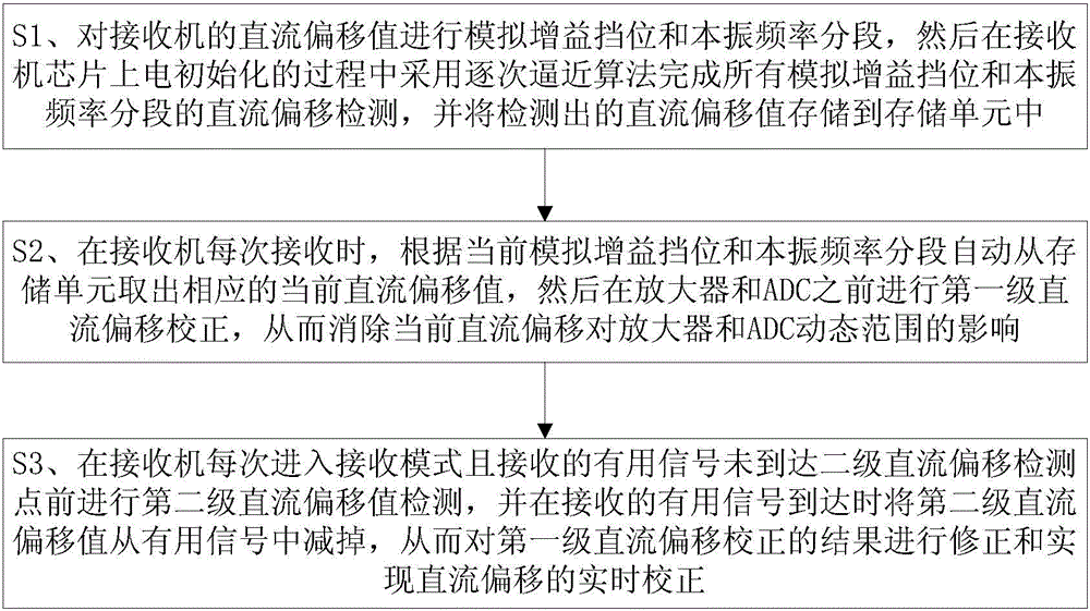
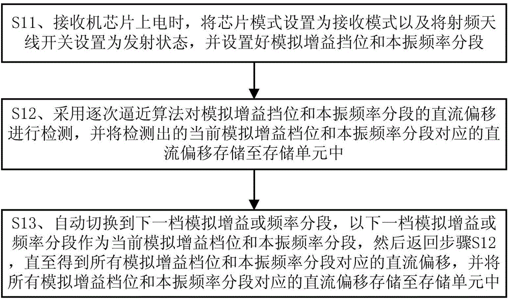
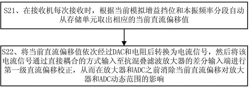
[0112] The present invention adopts a two-stage DC offset correction method and device: the first stage corrects the DC offset before the amplifier and ADC, avoiding the problem of non-linear distortion caused by saturation of the amplifier or ADC due to excessive DC; the second stage The second stage corrects the DC offset in real time after the amplifier and ADC on the basis of the first stage DC offset correction, which solves the problem of real-time DC changes caused by changes in the environment and temperature. In consideration of balancing precision, area, and power consumption, the successive approximation algorithm in this embodiment adopts a five-bit successive approximation algorithm, and the DAC adopts a five-bit DAC.

[0113] Concrete implementation process of the present invention is as follows:

[0114] (one). First-level DC offset correction method and device

[0115] The first level of DC offset correction is only done once when the receiver chip is powered...


PUM


Abstract

The invention discloses a DC deviation correcting method and device. The method comprises the steps of simulating a gain gear and a local oscillator frequency sections for the DC deviation value of a receiver; performing the gradually approaching algorithm during electrically initializing a receiver chip to finish the DC deviation detection of all simulated gain gear and the local oscillator frequency sections; storing the detected DC deviation values into a storage unit; automatically moving out the corresponding current DC deviation value from the storing unit according to the current simulated gain gear and the local oscillator frequency sections; performing the first-stage DC deviation correction before an amplifier and an ADC; performing the second-stage DC deviation value detection before a received usable signal reaches a second-stage DC deviation detecting point; subtracting the second-stage DC deviation value from the usable signal when the received usable signal arrives. The method and the device have the advantages that the dynamic ranges of the amplifier and the ADC cannot be reduced, and the real-time performance is high; the method and the device can be widely applied to the field of radio frequency communication.

Description

technical field [0001] The invention relates to the field of radio frequency communication, in particular to a DC offset correction method and device. Background technique [0002] Glossary: [0003] LNA: low noise amplifier; [0004] ADC: analog-to-digital converter; [0005] DAC: digital-to-analog converter; [0006] SAR: successive approximation; [0007] DC: DC offset; [0008] I: in-phase component; [0009] Q: quadrature component [0010] SAW Filter: SAW filter. [0011] The zero-IF receiver technology is relative to the traditional two-time frequency conversion technology, which only uses one frequency conversion. The working process of the zero-IF receiver is: the air signal passes through the antenna, the low-noise amplifier, and a mixer, and directly converts the in-band RF signal into a baseband analog IQ signal, and then converts it into a digital IQ signal through the ADC, and then performs Channel filtering, demodulation and decoding, etc. [0012] T...

Claims


Application Information

Patent Timeline
IPC IPC(8): H04L25/06
Inventor 叶晖李斌徐肯梁晓峰王昭黄沫
Owner SOUTH CHINA UNIV OF TECH
Why Eureka
Try Eureka