Optical fiber lighting intelligent illumination system

A technology of intelligent lighting and optical fiber, applied in the field of electronic devices, can solve the problems of high cost and high energy consumption of lighting, and achieve the effect of zero energy consumption and low cost

Inactive Publication Date: 2015-07-29
BEIHUA UNIV
View PDF5 Cites 4 Cited by
  • Summary
  • Abstract
  • Description
  • Claims
  • Application Information

AI Technical Summary

Problems solved by technology

[0003] The purpose of the present invention is to provide an intelligent lighting system for optical fiber l

Method used


Image

  • Optical fiber lighting intelligent illumination system
  • Optical fiber lighting intelligent illumination system
  • Optical fiber lighting intelligent illumination system

Examples


Example Embodiment

[0016] The present invention will be described in detail below in combination with specific embodiments.

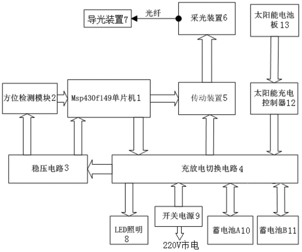
[0017] The system uses 16-bit ultra-low power consumption MSP430F149 microcontroller as the control core. figure 1 It is a schematic diagram of the module structure of the present invention. The system of the present invention comprises a MSP430F149 single-chip microcomputer 1, and the MSP430F149 single-chip microcomputer 1 is respectively connected with an orientation detection module 2, a voltage stabilizing circuit 3, a charge-discharge switching circuit 4 and a transmission device 5, and the transmission device 5 is connected with a daylighting device 6, and the daylighting device 6 is connected with a light guide device 7, The voltage stabilizing circuit 3 is respectively connected to the orientation detection module 2 and the charging and discharging switching circuit 4, and the charging and discharging switching circuit 4 is respectively connected to the LED lighti...


PUM


Abstract

The invention discloses an optical fiber lighting intelligent illumination system. An MSP430F149 single-chip microcomputer is connected with a direction detection module, a voltage stabilization circuit, a charging and discharging switching circuit and a transmission device. The transmission device is connected with a lightning device which is connected with a light guide device. The voltage stabilization circuit is connected with the direction detection module and the charging and discharging switching circuit. The charging and discharging switching circuit is connected with an LED illumination module, a switch power supply module, a storage battery A, a storage battery B and a solar charging controller. The solar charging controller is connected with a solar cell panel. The direction detection module detects the deviation angle, relative to sunlight, of the lightning device. The single-chip microcomputer receives signals detected by the direction detection module and drives a pan-tilt of the transmission device to act so that the lighting device can be accurately aligned with the sun. Meanwhile, charging and discharging switching is achieved by controlling the charging and discharging switching circuit according to the electricity amounts of the storage batteries. The optical fiber lighting intelligent illumination system has the advantages that cost is low, and zero energy consumption is achieved.

Description

technical field [0001] The invention belongs to the technical field of electronic devices, and relates to an optical fiber lighting intelligent lighting system. Background technique [0002] In recent years, as urban buildings tend to be high-rise and dense, traditional lighting methods alone cannot meet the lighting requirements inside buildings. Especially in low-rise buildings, windowless rooms and basements, even in sunny weather, the interior is dark and gloomy, which increases the power consumption of artificial lighting invisibly, and affects the physical and mental health of people who live and work in this environment for a long time. bring adverse effects. Contents of the invention [0003] The object of the present invention is to provide an optical fiber lighting intelligent lighting system, which solves the problems of high energy consumption and high cost of lighting in existing buildings. [0004] The technical scheme adopted in the present invention compr...

Claims


Application Information

Patent Timeline
IPC IPC(8): H05B37/02
CPCY02B20/40
Inventor 高崧刘德君钱云毕红白晶姜丰程诚王江攀
Owner BEIHUA UNIV
Why Eureka
Try Eureka