
Center clamping device for tube bending machines

A clamping device and bending machine technology, which is applied in the mechanical field, can solve the problems of large forward and reverse errors, low rotation accuracy, and large equipment power requirements, so as to avoid accumulated errors, avoid rotation errors, and improve bending quality. Effect

Active Publication Date: 2016-08-17
JIANGSU UNIV OF SCI & TECH IND TECH RES INST OF ZHANGJIAGANG +1
View PDF5 Cites 0 Cited by
  • Summary
  • Abstract
  • Description
  • Claims
  • Application Information

AI Technical Summary

Problems solved by technology

[0004] At present, the structure of the central clamping device used in the pipe bending machine is relatively complicated, the processing and installation are difficult, the power transmission system is unstable, and the forward and reverse errors of the turning gear plate are relatively large (the rotation accuracy is low), which leads to the unevenness of the finished pipe. Meet the requirements, eventually resulting in an increase in the cost of pipe production
For example: the Chinese patent with the publication number CN203281764 U discloses an automatic bending machine, which adopts a rotary clamping mechanism that can rotate 360 ​​degrees around the axis of the conveying metal pipe, and the shearing mechanism and bending mechanism of the equipment The mechanism is also located on the rotating mechanism at the same time, which leads to the extremely complicated structure of the whole equipment, which is not conducive to installation, and the power demand of the equipment is relatively large, and the manufacturing cost is also high

Method used


Image

  • Center clamping device for tube bending machines
  • Center clamping device for tube bending machines
  • Center clamping device for tube bending machines

Examples


Embodiment Construction

[0022] Specific embodiments of the present invention will be described in detail below in conjunction with the accompanying drawings.

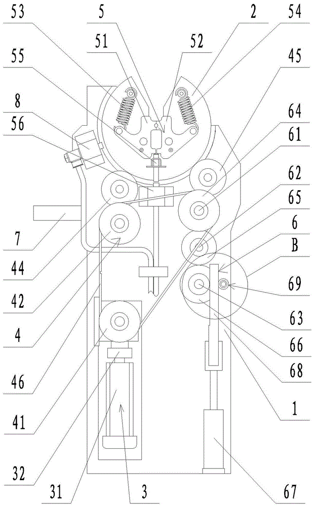
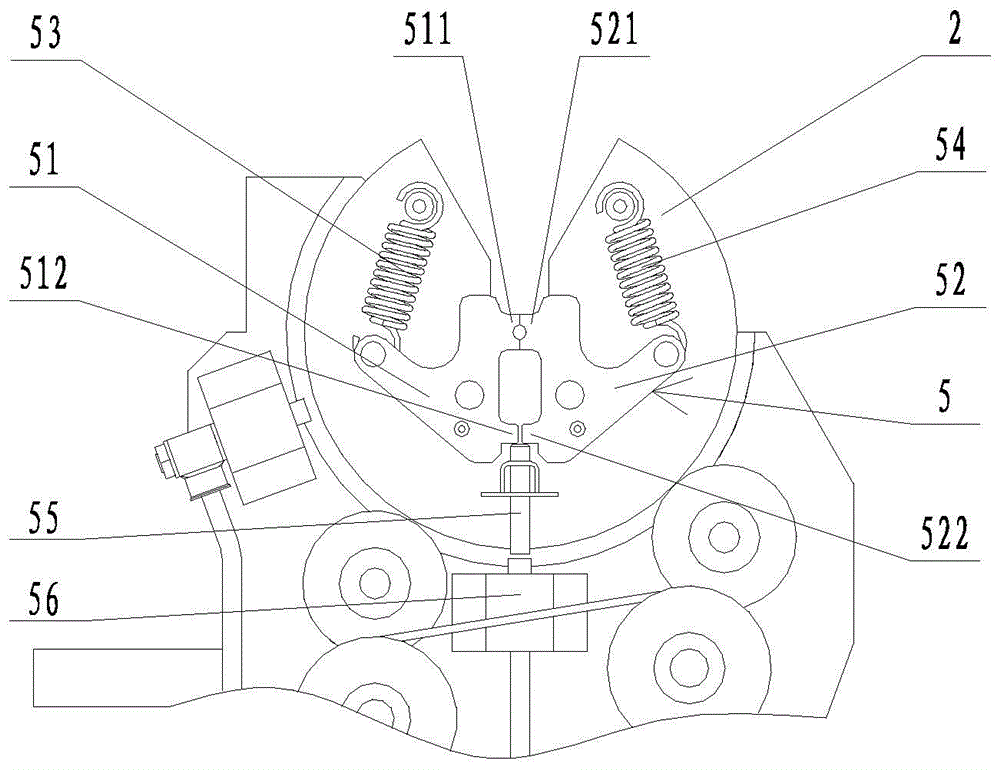
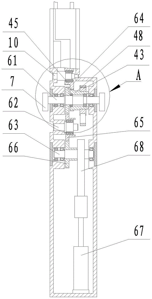
[0023] Such as figure 1 , Figure 3 ~ Figure 5 The shown central clamping device for a pipe bending machine includes a box body 1, a rotating gear plate 2 set on the box body 1, a power device 3 set on the box body 1, connecting the rotating gear plate 2 and the power The transmission mechanism 4 of the device 3, and the clamping mechanism 5 arranged on the rotating gear plate 2 for clamping the pipe, the transmission mechanism 4 includes a main synchronous pulley 41 fixedly connected to the output shaft of the power device 3, respectively The left transition gear 44 and the right transition gear 45 meshed with the rotary gear plate 2, the left transmission gear 47 meshed with the left transition gear 44, and the right transmission gear 48 meshed with the right transition gear 45 are coaxial with the left transmission gear 47 and rotate synch...


PUM


Abstract

Disclosed is a center clamping device for a pipe bending machine. The center clamping device for the pipe bending machine comprises a box body, a rotating gear disk, a power device, a transmission mechanism and a clamping mechanism. The transmission mechanism comprises a main synchronous belt wheel, a left transition gear, a right transition gear, a left transmission gear, a right transmission gear, a left synchronous belt wheel, a right synchronous belt wheel and a synchronous belt, wherein the main synchronous belt wheel is fixedly connected to an output shaft of the power device, the left transition gear and the right transition gear are meshed with the rotating gear disk, the left transmission gear is meshed with the left transition gear, the right transmission gear is meshed with the right transition gear, the left synchronous belt wheel and the left transition gear are coaxial, and synchronously rotate, the right synchronous belt wheel and the right transmission gear are coaxial, and synchronously rotate, and the main synchronous belt wheel, the left synchronous belt wheel and the right synchronous belt wheel are connected through the synchronous belt. The left transition gear is connected to the box body through a first transition shaft, and the right transition gear is connected to the box body through a second transition shaft. According to the invention, transmission is stable, maintenance is convenient, the error generated by the rotating gear disk in the forward and backward rotation process is eliminated, and the rotating accuracy is improved.

Description

technical field [0001] The invention relates to the mechanical field, in particular to a central clamping device for a pipe bending machine. Background technique [0002] Pipe bending machine is a common manufacturing process in the field of machinery manufacturing. It is used to bend pipes into target products with specific angles. The products are widely used in important fields such as aerospace, automobiles, ships, and construction machinery. [0003] The role of the central clamping device of the pipe bending machine in the whole machine is mainly to clamp the pipe and continuously adjust the angle of the pipe relative to the bending head, so as to match the bending mechanism at both ends of the central clamping device on the pipe. The bending action, the stability and rotation accuracy of the central clamping device directly affect the quality of the pipe bending. [0004] At present, the structure of the central clamping device used in the pipe bending machine is rel...

Claims


Application Information

Patent Timeline
Patent Type & Authority Patents(China)
IPC IPC(8): B21D7/16B21D43/00
CPCB21D7/16B21D43/003
Inventor 唐文献林洪才张建周瑞张阳齐继阳林永才叶福民
Owner JIANGSU UNIV OF SCI & TECH IND TECH RES INST OF ZHANGJIAGANG
Learn More