
Rapid locking mechanism

A technology of fast locking and locking studs, which is applied in the direction of mechanical equipment, metal processing machinery parts, clamping, etc., can solve problems such as restrictions or inconvenient operation, large internal space size, and unrealizable problems, so as to achieve convenient operation and parts Easy installation and disassembly, small space occupation

Active Publication Date: 2015-08-05
HUBEI SANJIANG AEROSPACE WANFENG TECH DEV
View PDF5 Cites 7 Cited by
  • Summary
  • Abstract
  • Description
  • Claims
  • Application Information

AI Technical Summary

Problems solved by technology

The disadvantage is: the installation position, installation method and shape of the parts on the machine tool table have certain restrictions. After the locking mechanism is released, the position of the parts and the locking pressure plate cannot be completely separated, and the parts need to be moved to the locking pressure plate first. In order to carry parts up and down, this kind of mechanism occupies a large internal space
[0006] The above methods of fastening parts on the workbench all have certain limitations or are inconvenient to operate, especially when the fixed position of the parts is not easy to reach by hand or tools, or when the parts are in an inclined position, at this time on the workbench It will be very difficult or impossible to fix and remove the parts

Method used


Image

  • Rapid locking mechanism
  • Rapid locking mechanism
  • Rapid locking mechanism

Examples


Embodiment Construction

[0027] In order to make the object, technical solution and advantages of the present invention clearer, the present invention will be further described in detail below in conjunction with the accompanying drawings and embodiments. It should be understood that the specific embodiments described here are only used to explain the present invention, not to limit the present invention. In addition, the technical features involved in the various embodiments of the present invention described below can be combined with each other as long as they do not constitute a conflict with each other.

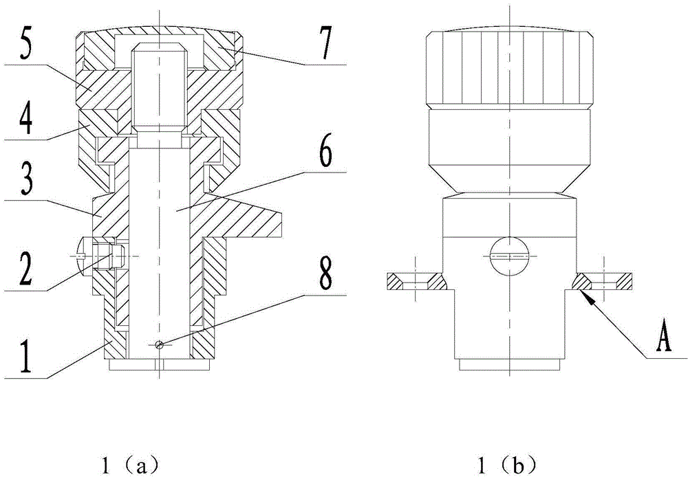
[0028] The preferred embodiment of the present invention is a manual quick lock mechanism on the test bench, which is used for manual fast locking of test parts on the test bench. The test part is in the shape of a ring, and the test part on it is installed and disassembled by moving up and down. There are three manual quick lock mechanisms evenly distributed around the test part.

[0029] Such...


PUM


Abstract

The invention discloses a rapid locking mechanism. The rapid locking mechanism comprises a fixed base of a hollow annular structure, a locking stud with the bottom end fixed into an annular cavity of the fixed base, a locking nut arranged at the upper end of the locking stud in a sleeving mode, a limiting ring arranged on the locking stud in a sleeving mode, and a guide locking mechanism. The upper end of the limiting ring is connected with the lower end of the locking nut. The guide locking mechanism comprises a guide locking pressing column and a guide screw, wherein the guide locking pressing column is arranged on the locking stud in a sleeving mode, the upper end of the guide locking pressing column is connected with the lower end of the limiting ring, the middle of the guide locking pressing column protrudes outwards to form a pressing table, a spiral groove is machined in the side wall of the lower portion of the pressing table, the tail portion of the spiral groove is connected with a linear section groove, one end of the guide screw is fixed to the fixed base, and the other end of the guide screw extends into the linear section groove and the spiral groove of the guide locking pressing column. The guide locking mechanism can rotate up and down by rotating the nut so that the guide locking mechanism can get close to parts to press the parts or get away from the parts to release the parts. The rapid locking mechanism is reliable in locking and convenient to operate, and is not limited by the installation positions or shapes of the parts.

Description

technical field [0001] The invention belongs to the technical field of mechanical equipment, and in particular relates to a manual quick locking mechanism, which is used for quick locking of parts or equipment on a workbench. Background technique [0002] At present, operating instruments, equipment, and parts to be processed are installed on many machine tool workbenches, test platforms, equipment mounting brackets, and tripods. If they need to be installed and disassembled manually, a set of manual quick locks must be installed and fixed on them. The mechanism can be installed and fixed or disassembled at any time. Taking fixing parts on the machine tool table as an example, according to the searched information and patents, there are mainly the following methods: [0003] At present, the most commonly used method is to fix the parts on the machine tool table through the combination of the pressure plate and the fixing bolt. the goal of. The advantage of this method is ...

Claims


Application Information

Patent Timeline
Patent Type & Authority Applications(China)
IPC IPC(8): B23Q3/06B25B11/00F16B1/04
CPCB23Q3/069B25B11/00F16B1/04
Inventor 李海峰刘莹马柯李兰春付勇王亚飞翟宏延
Owner HUBEI SANJIANG AEROSPACE WANFENG TECH DEV
Learn More