
A sign marking vehicle

A line marking car and marking technology, applied in the field of marking and marking cars, can solve the problems of high production cost, short use time, large and complex structure of the marking machine, etc., and achieve the effect of strong applicability

Inactive Publication Date: 2017-01-11
ZHEJIANG OCEAN UNIV
View PDF1 Cites 0 Cited by
  • Summary
  • Abstract
  • Description
  • Claims
  • Application Information

AI Technical Summary

Problems solved by technology

[0003] Such as the Chinese invention patent application (application number: 201110158532.4) discloses a ride-on type hot-melt spraying marking machine, including a frame, which is equipped with a power drive system, a heating system, a marking system and a walking system. The frame is also equipped with a hydraulic control system, a pneumatic control system and a steering system. The power drive system is respectively connected to the walking system, hydraulic control system and pneumatic control system. The hydraulic control system is connected to the steering system. The marking system is connected to the hydraulic The control system and the air pressure control system are connected by transmission. This invention makes full use of the hot-melt spray paint to be heated into a molten state by the infrared heating system and the heat-conducting oil heat preservation circulation system, and then sprayed to the designated place by the hot-melt spray gun. The marking efficiency is high, but the The overall structure of the marking machine is huge and complex, and the production cost is relatively high. It is suitable for large-scale marking, such as highways, etc., but it is not suitable for small areas such as internal district divisions and short-term use occasions.

Method used


Image

  • A sign marking vehicle
  • A sign marking vehicle
  • A sign marking vehicle

Examples


Embodiment Construction

[0028] The following are specific embodiments of the present invention and in conjunction with the accompanying drawings, the technical solutions of the present invention are further described, but the present invention is not limited to these embodiments.

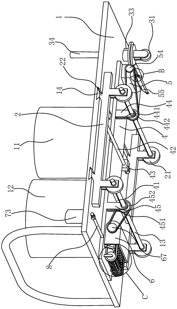
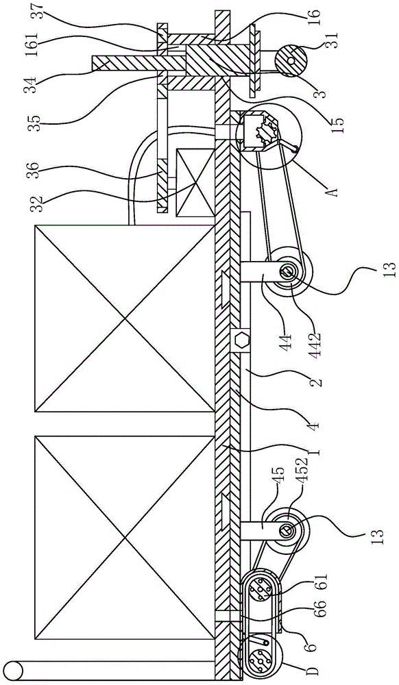
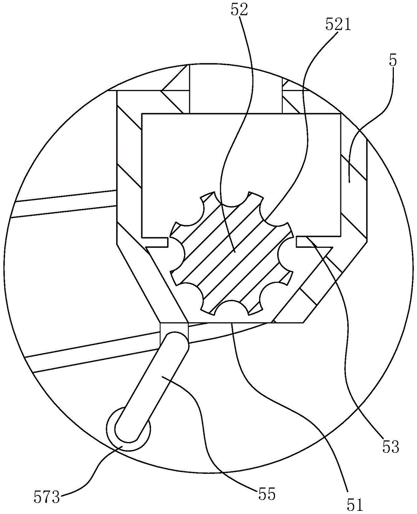
[0029] Such as Figure 1 to Figure 6 As shown, a marking and marking vehicle includes a rectangular base 1, a heating barrel 11 for storing marking paint and a raw material barrel 12 for storing reflective debris are fixedly connected to the upper side of the base 1, and the lower side of the base 1 is rotatably connected There are two main shafts 13, the axial direction of the two main shafts 13 is consistent with the width direction of the base 1, two moving rods 2 are slidably connected to the lower side of the base 1, the two moving rods 2 are perpendicular to the main shaft 13, and the moving rods 2 are hinged with Two moving wheels 21, and the moving wheels 21 are all connected with the main shaft 13 in transmission,...


PUM


Abstract

The invention provides a road line-marking vehicle, belongs to the technical field of road operation equipment and solves a problem of a poor adaptability of a road marking vehicle in the prior art. The road line-marking vehicle includes a pedestal. A heating barrel and a raw material barrel are fixedly connected to an upper side surface of the pedestal. Two main shafts are rotationally connected to a lower side surface of the pedestal. Two moving rods are slidingly connected to the lower side surface of the pedestal. Each moving rod is hinged to two moving wheels. A moving plate is slidingly connected to the lower side surface of the pedestal. A line-marking box is fixedly connected to a front end of the moving plate. A material discharge outlet is formed in the lower part of the line-marking box. A metering member is arranged in the line-marking box. A bottom shell is fixedly connected to the lower side surface of a back end of the moving plate and is rotatably connected to a front transmission wheel and a back transmission wheel, a transmission net is arranged therebetween in a sleeving manner. A gas spraying tube is fixedly connected to the bottom shell. The road line-marking vehicle is simple in structure, is convenient to use and is strong in adaptability.

Description

technical field [0001] The invention belongs to the technical field of road operation equipment, and relates to a marking and marking vehicle. Background technique [0002] With the increase of car ownership, traffic regulations are becoming more and more important. For example, road traffic signs and markings are an infrastructure that guides road users to use the road in an orderly manner to promote road traffic safety and improve road operation efficiency. It is used to inform road users of the right to pass on the road, express road traffic prohibitions, restrictions, and compliance conditions, and announce road conditions and traffic conditions. It is a traffic safety facility composed of surface markings, raised road signs and outline signs, etc. Its function is to control and guide traffic, and it can be used in conjunction with signs or alone. Marking lines are usually marked with marking paint. The marking paint has the advantages of good adhesion to the road surfa...

Claims


Application Information

Patent Timeline
Patent Type & Authority Patents(China)
IPC IPC(8): E01C23/22
Inventor 叶鹏鹏郑雄胜车佳幸
Owner ZHEJIANG OCEAN UNIV
Learn More