Abrasion resistant test machine for cattle leather
A wear-resistant test and leather technology, which is applied in the field of test equipment, can solve problems such as troublesome installation of the product to be tested, imperfect friction tester, and complex overall structure.
- Summary
- Abstract
- Description
- Claims
- Application Information
AI Technical Summary
Problems solved by technology
Method used
Image
Examples
Embodiment 1
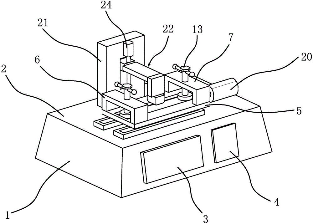
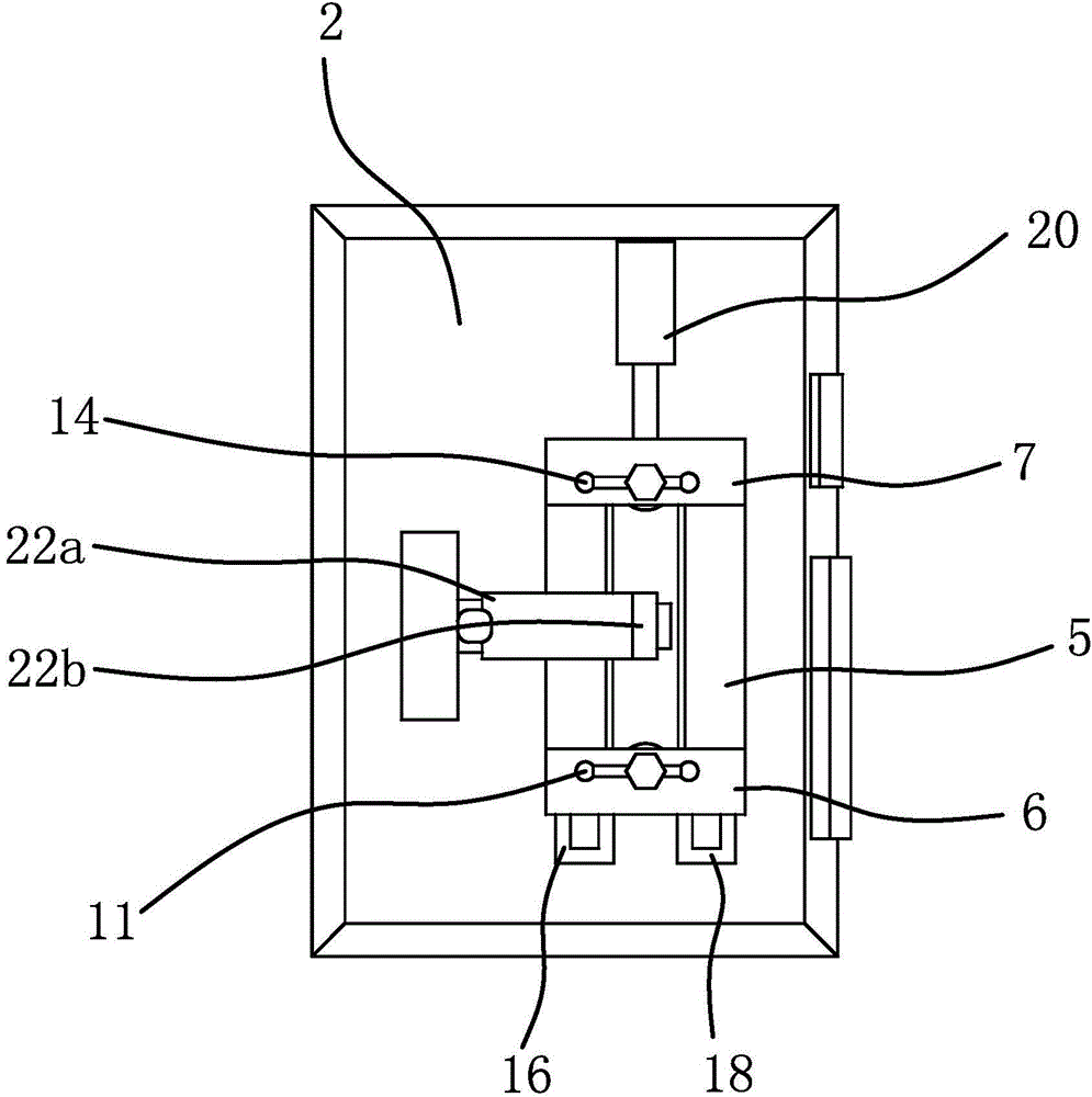
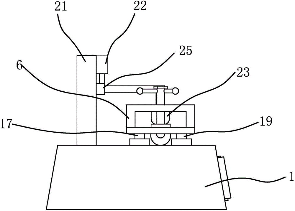
[0030] Such as figure 1 , figure 2 and image 3 As shown, a cow leather wear tester includes a body 1 and a workbench 2 arranged on the body 1 , and a display 3 and a control panel 4 are also arranged on the body 1 . The workbench 2 is provided with a clamping mechanism capable of clamping the cowhide, and the workbench 2 is also provided with a drive mechanism capable of driving the installation panel 5 to reciprocate and a friction test device capable of performing a friction test on the cowhide.
[0031] Such as Figure 4As shown, specifically, the clamping mechanism includes a mounting panel 5 slidably arranged on the workbench 2 , and clamping block 1 6 and clamping block 2 7 symmetrically fixed on both sides of the mounting panel 5 . Wherein, the installation panel 5 is provided with an installation groove 8 for installing cow leather along its length direction, and a heating sheet 9 is fixed in the installation groove 8, and the width of the heating sheet 9 is small...
Embodiment 2
[0039] This embodiment is basically the same as the driving mechanism and principle of the first embodiment, the difference is: in the first embodiment, the driving mechanism is to push the cylinder 20; and in the second embodiment, as Figure 5 As shown, the drive mechanism includes a rotating motor 27, a cam 28, and a connecting rod 29. The motor is fixed on the above-mentioned workbench 2, and the cam 28 is fixed on the output shaft of the rotating motor 27. The connecting rod 29 One end of the connecting rod is hinged on the cam 28, and the other end of the connecting rod 29 is hinged on the side wall of the mounting panel 5. The rotating motor 27 drives the cam 28 to rotate, and the circumferential motion is converted into a horizontal motion under the action of the connecting rod 29, so that the installation panel 5 can reciprocate on the first slide rail 16 and the second slide rail 18.
Embodiment 3
[0041] This embodiment is basically the same as the lifting and positioning mechanism and principle of the first embodiment, the difference is: in the first embodiment, the lifting and positioning mechanism is a lifting cylinder 24; and in the second embodiment, the lifting and positioning mechanism is a push rod Motor, the push rod motor is fixed on the adjusting plate 21, the push rod of the push rod motor is vertically downward and parallel to the groove, and the push rod end of the push rod motor is fixed on the upper surface of the slide block 25. Through the push rod of the push rod motor, the sliding block 25 can be driven to slide in the groove of the adjusting plate 21 .
PUM
 Abstract
Description
Claims
Application Information
 - R&D
- Intellectual Property
- Life Sciences
- Materials
- Tech Scout
- Unparalleled Data Quality
- Higher Quality Content
- 60% Fewer Hallucinations
Browse by: Latest US Patents, China's latest patents, Technical Efficacy Thesaurus, Application Domain, Technology Topic, Popular Technical Reports.
© 2025 PatSnap. All rights reserved.Legal|Privacy policy|Modern Slavery Act Transparency Statement|Sitemap|About US| Contact US: help@patsnap.com


