Device and method for measuring blood flow of blood vessels

A blood flow and blood vessel technology, applied in the field of optoelectronics, can solve the problems of cumbersome background removal process, inapplicability of frequency-domain OCT system, and difficulty in ensuring the accuracy of background removal, so as to save extra work and errors, and avoid excessive high-frequency background Puller's effect

Active Publication Date: 2015-08-12
SHENZHEN CERTAINN TECH CO LTD
View PDF6 Cites 13 Cited by
  • Summary
  • Abstract
  • Description
  • Claims
  • Application Information

AI Technical Summary

Problems solved by technology

The disadvantage of this method is that it is not applicable to the frequency domain OCT system due to the time delay between the two paths of light.
This not only makes the background removal process more cumbersome, but also makes it difficult to guarantee the accuracy of background removal
The background error detection will directly affect the accuracy of blood flow velocity measurement in blood vessels.

Method used


Image

  • Device and method for measuring blood flow of blood vessels
  • Device and method for measuring blood flow of blood vessels
  • Device and method for measuring blood flow of blood vessels

Examples


no. 1 Embodiment

[0093] The first embodiment: the optical path translation device 502 is a glass plate with both ends beveled .

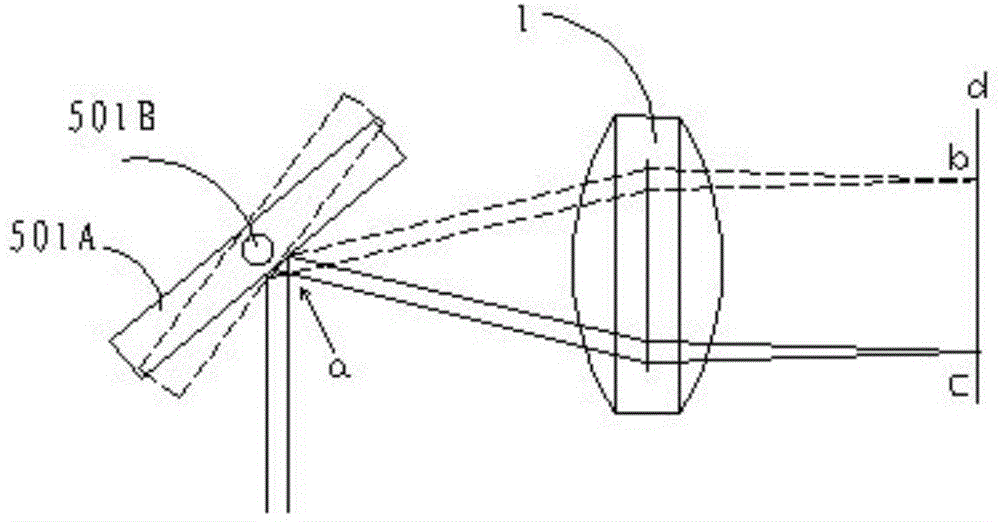
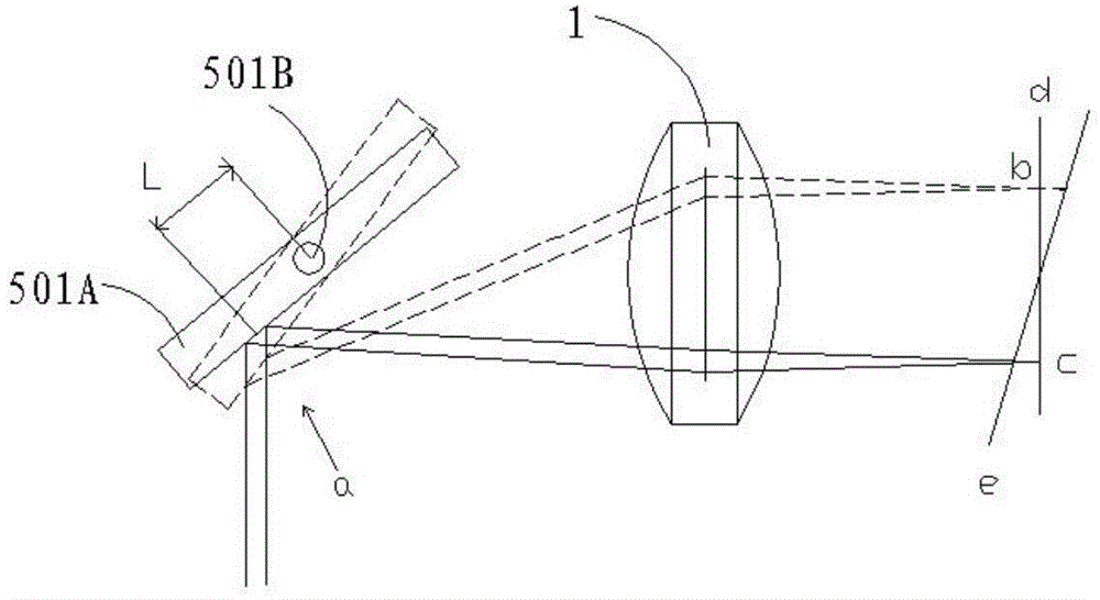
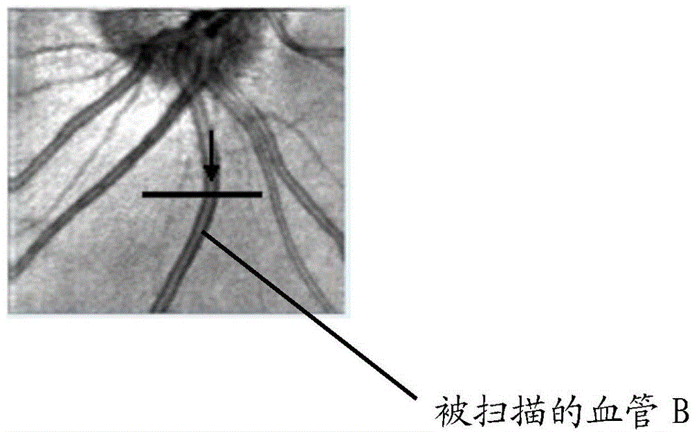
[0094] Please refer to Figure 7 , when measuring the blood flow velocity of the blood vessel B, when the optical path translation device 502 is in the first position, the main light ray 50 of the probe light is incident on the rotation axis of the scanning unit 501, is reflected by the scanning unit 501 to the optical path translation device 502, and is translated in the optical path After the incident surface 502A of the device 502 is refracted, the detection light is refracted again by the exit surface 502B of the optical path translation device 502, and the refracted detection light scans one of the blood vessels B of the eye 800 in the first direction S1 and along the Y direction (see Figure 13 ). After the scan is completed, the detection light carries the signal of blood vessel B, scatters through the fundus, and returns to the original path Figure 6 Th...

no. 2 Embodiment

[0096] The second embodiment: the optical path translation device 502 is two mirrors distributed in parallel .

[0097] refer to Figure 9 and Figure 10 , and the difference from the first embodiment is that the optical path translation device 502 is composed of two first reflective mirrors 502D and second reflective mirrors 502E arranged in parallel. Please refer to Figure 9 , when the optical path translation device 502 is in the first position, the principal ray 50 of the probe light is incident on the rotation axis of the scanning unit 501, is reflected to the optical path translation device 502 through the scanning unit, and is reflected to the second reflection mirror 502E by the first mirror 502D , and then emitted by the second mirror 502E, the detection light scans one of the blood vessels B of the eye 800 in the first direction S1 and along the Y direction (see Figure 13 ). After the scan is completed, the detection light carries the signal of blood vessel B...

no. 3 Embodiment

[0099] The third embodiment: the optical path translation device 502 is a prism .

[0100] refer to Figure 11 , when the optical path translation device 502 is in the first position, the principal ray 50 of the probe light is incident on the rotation axis of the scanning unit 501 , and is reflected to the optical path translation device 502 through the scanning unit 501 . At this time, the optical path translation device 502 is a prism. The detection light is reflected from the first reflection surface 502F of the prism to the second reflection surface 502G, and then exits from the second reflection surface 502G. The detection light scans one of the blood vessels B of the eye 800 in the first direction S1 and along the Y direction. After the scan is completed, the detection light carries the signal of blood vessel B, which is reflected by the fundus and returns to the original path. Figure 6 The spectroscopic module 200 in , and the reference light returned from the refe...


PUM


Abstract

The invention discloses a device and method for measuring the blood flow of blood vessels. The method includes the steps that a light source, a light splitting module, a reference arm module, a sample arm module, a detection module and a control system are arranged on a light path; the sample arm module mainly comprises a scanning unit and a rotatable light path transverse movement device; detection light is obtained after light of the light source passes through the light splitting module, wherein the main light of the detection light is located on a rotating shaft of the scanning unit all the time; the detection light is scanned by the scanning unit to be reflected to the light path transverse movement device, when the light path transverse movement device is located at a first position and a second position, the eye ground blood vessels are scanned, a first phase signal and a second phase signal of the measured blood vessels are obtained, and finally the blood flowing speed and the blood flow of single blood vessels and the blood flow of all the blood vessels nearby an optic disk are solved according to formulas. By means of the device and method, the high-frequency background Doppler effect of collected original Doppler images of the blood vessels is avoided, and extra work and errors caused by removing the high-frequency background Doppler effect are eliminated.

Description

technical field [0001] The invention relates to the field of optoelectronic technology, in particular to a device and method for measuring blood flow in blood vessels. Background technique [0002] Many retinal diseases are associated with abnormal blood flow to the eye, such as diabetic retinopathy, retinal vein occlusion, and age-related macular degeneration. In glaucoma research, retinal insufficiency is considered a possible cause of glaucoma occurrence and development. Therefore, the measurement of retinal blood flow is of great significance for the clinical diagnosis, treatment and research of retinal diseases. [0003] Optical coherence tomography (Optical Coherence Tomography, OCT) is a non-invasive detection technology, which is widely used in living body cross-sectional structure imaging. By measuring depth-dependent scattered light, OCT can provide high-resolution, high-sensitivity tissue structures. At the same time, OCT technology can also detect the Doppler ...

Claims


Application Information

Patent Timeline
Patent Type & Authority Applications(China)
IPC IPC(8): A61B5/0265A61B5/0285
CPCA61B3/1233A61B3/1241A61B3/14A61B5/0062A61B5/026A61B5/7203G01B9/02076A61B5/7207A61B3/102A61B5/0066A61B5/0261G01B9/02091G01B9/0201G01B9/0203G01B9/02044G01N21/4795
Inventor 郭曙光万明明李鹏代祥松张德兴
Owner SHENZHEN CERTAINN TECH CO LTD
Why Eureka
Try Eureka