Method for controlling SCARA (selective compliance assembly robot arm) based on movement controller
A motion controller and control method technology, applied in manipulators, manufacturing tools, etc., can solve the problems of high technical difficulty, long development cycle and high cost, and achieve the effect of simplifying motion algorithm, low cost and reducing development difficulty
- Summary
- Abstract
- Description
- Claims
- Application Information
AI Technical Summary
Problems solved by technology
Method used
Image

Examples
Embodiment Construction
[0038] In order to facilitate the understanding of those skilled in the art, the present invention will be further described below in conjunction with the embodiments and accompanying drawings, and the contents mentioned in the embodiments are not intended to limit the present invention. see Figure 1 to Figure 6 , the present invention will be described in detail below in conjunction with the accompanying drawings.
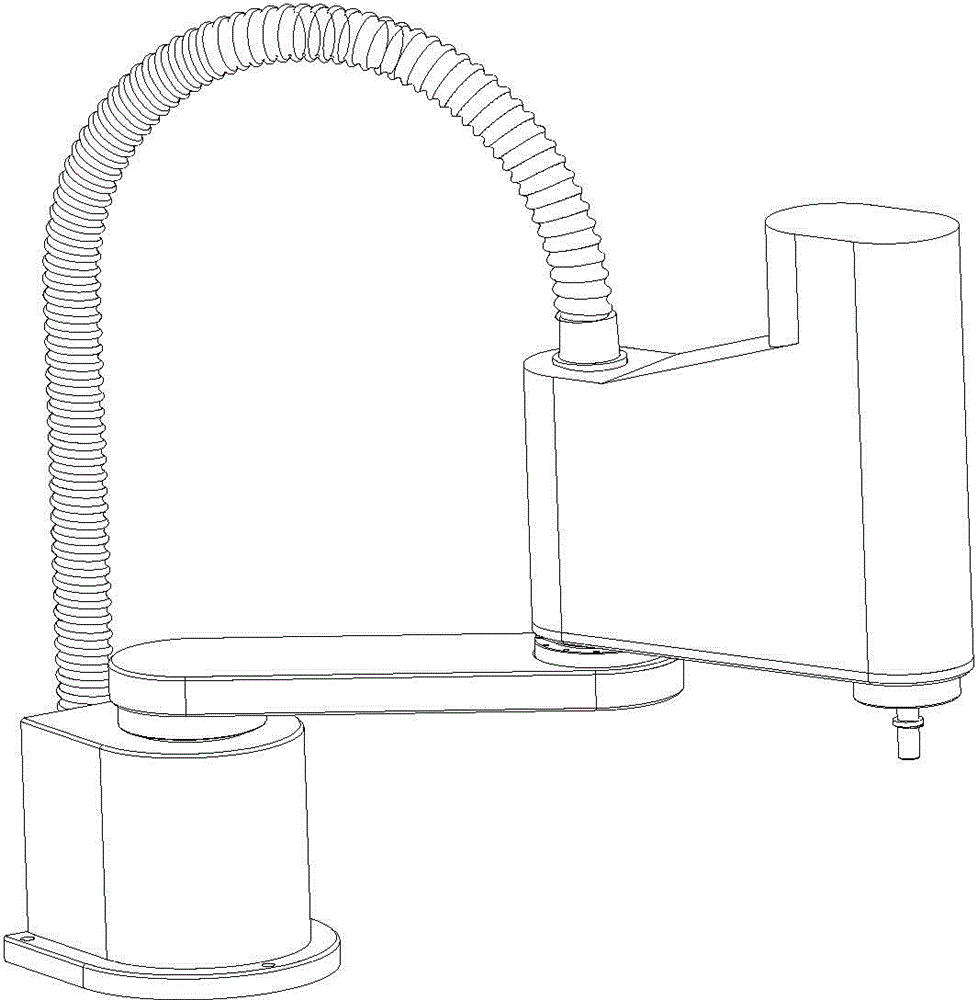
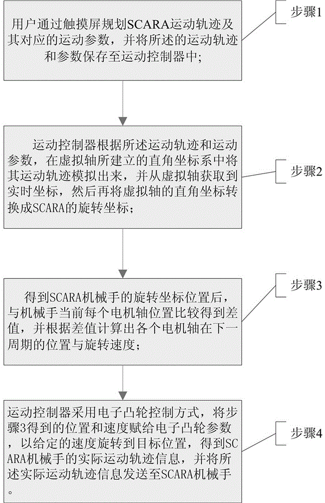
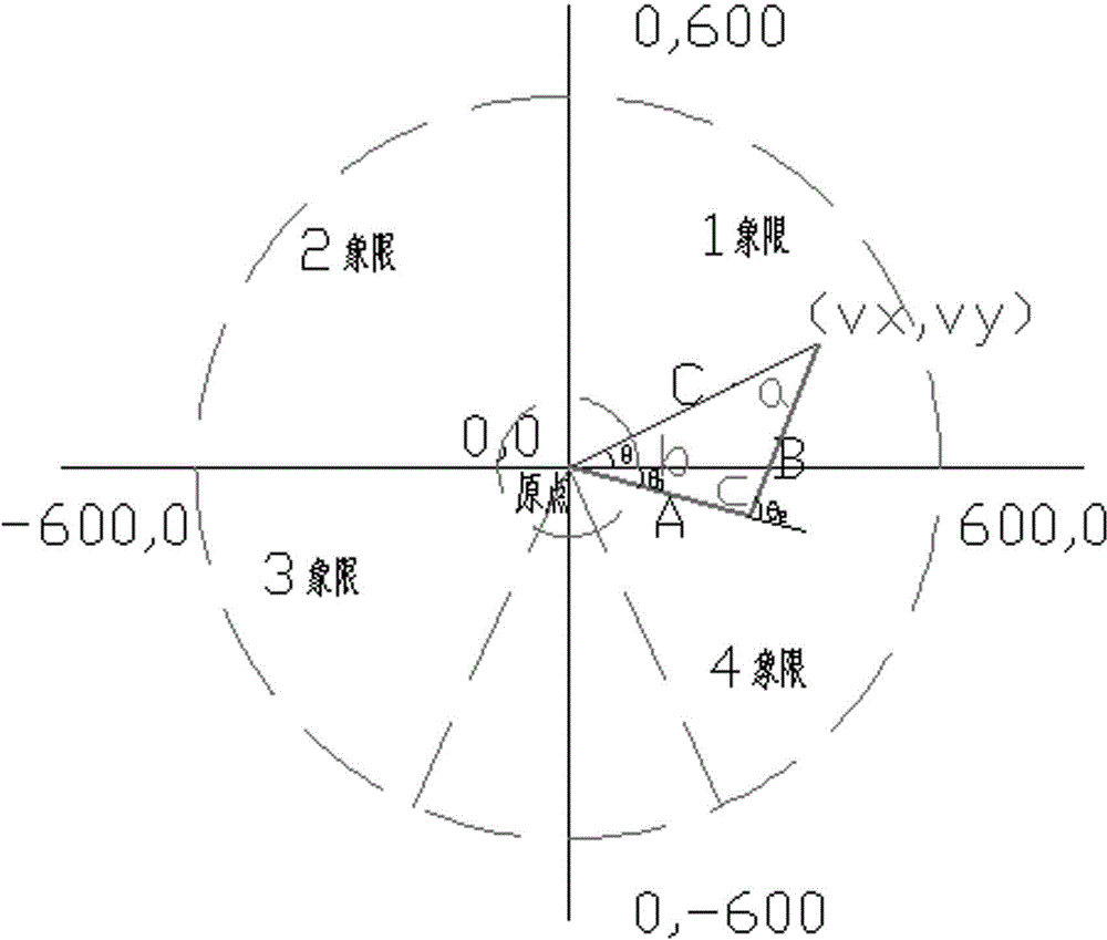
[0039] A SCARA manipulator control method based on a motion controller provided by the present invention includes a motion controller and an industrial touch screen, and the touch screen has secondary development functions such as position display, teaching, route planning, and general IO input and output. The motion controller communicates with the touch screen through the Ethernet communication port, and the steps of the control method are as follows:
[0040] Step 1: The user plans the trajectory of the SCARA manipulator and its corresponding motion parameter...
PUM
 Abstract
Description
Claims
Application Information
PatSnap Eureka turns technology decisions into work you can execute. Powered by our Innovation Knowledge Graph, it runs expert workflows across engineering, life sciences, materials and intellectual property. Get your review-ready output in minutes.


