
Industrial vehicle and traveling mechanism thereof

A technology for industrial vehicles and running mechanisms, applied to vehicle components, wheels, motor vehicles, etc., can solve the problems of poor environmental adaptability and single walking mode, and achieve the effect of simple structure and easy implementation.

Inactive Publication Date: 2015-08-12
ZHEJIANG DAMON TECH CO LTD
View PDF8 Cites 0 Cited by
  • Summary
  • Abstract
  • Description
  • Claims
  • Application Information

AI Technical Summary

Problems solved by technology

[0003] However, this type of transport vehicle has a single walking mode and poor environmental adaptability.

Method used


Image

  • Industrial vehicle and traveling mechanism thereof
  • Industrial vehicle and traveling mechanism thereof
  • Industrial vehicle and traveling mechanism thereof

Examples


Embodiment 1

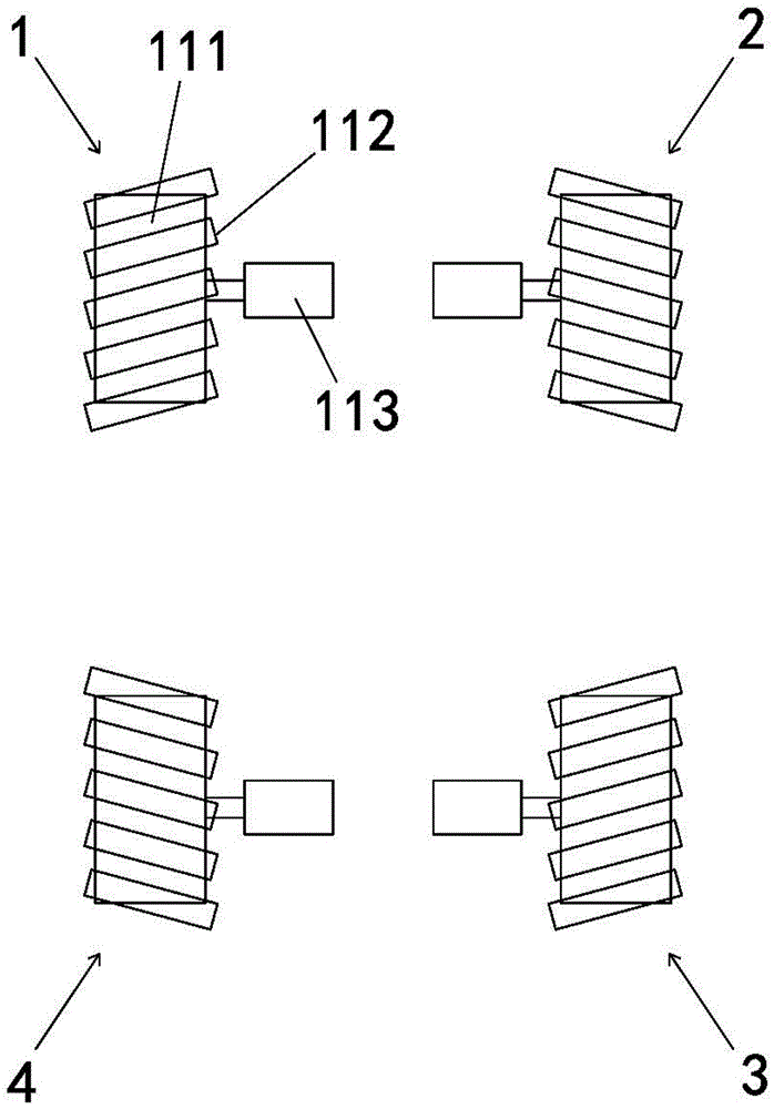
[0026] Embodiment 1: An industrial vehicle running mechanism, including at least four wheel sets, the closed-loop connection line of the four wheel sets is a quadrangle, and the quadrangle is a rectangle in this embodiment; figure 1 As shown, the four wheel sets are respectively the first wheel set 11, the second wheel set 12, the third wheel set 13, and the fourth wheel set 14; the first wheel set 11 and the third wheel set 13 are diagonally distributed, The second wheel set 12 and the fourth wheel set 14 are arranged diagonally.

[0027] The four wheel sets have the same structure, and all include a driving wheel 111, a plurality of driven wheels 112 that can be driven to rotate by the friction force generated between the driving wheel 111 and distributed along the circumferential direction of the driving wheel 111, and the driven wheels 112 are rotatably connected to Driving wheel 111; the walking medium is generally the ground.

[0028] The axis of the driven wheel 112 of...

Embodiment 2

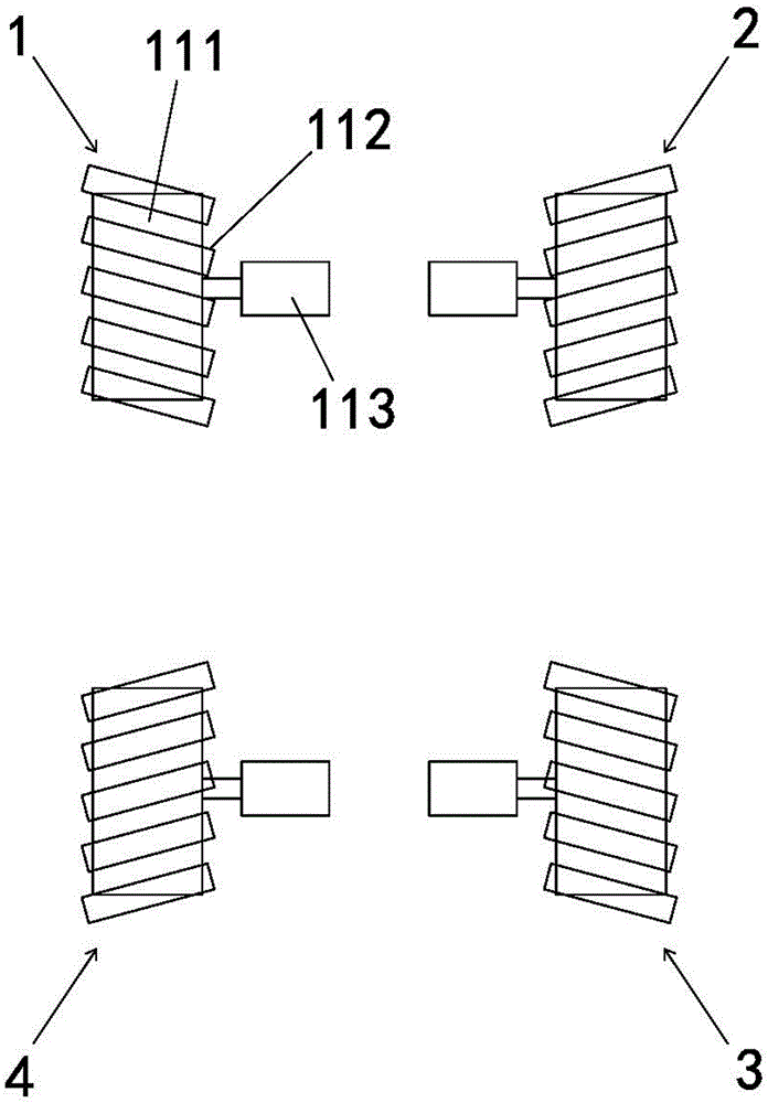
[0037] Embodiment 2: The difference with Embodiment 1 is that, as figure 2 As shown, with any sideline of the quadrilateral as the boundary line, the side close to the center of the industrial vehicle is the inner side, and the other side is the outer side; The inner side; the axis of the driven wheel 112 of the first wheel set 11 can be parallel or coincident with the axis of the driven wheel 112 of the third wheel set 13; the axis of the driven wheel 112 of the second wheel set 12 can be parallel or coincident with the fourth The axis of the driven wheel 112 of the wheel set 14.

Embodiment 3

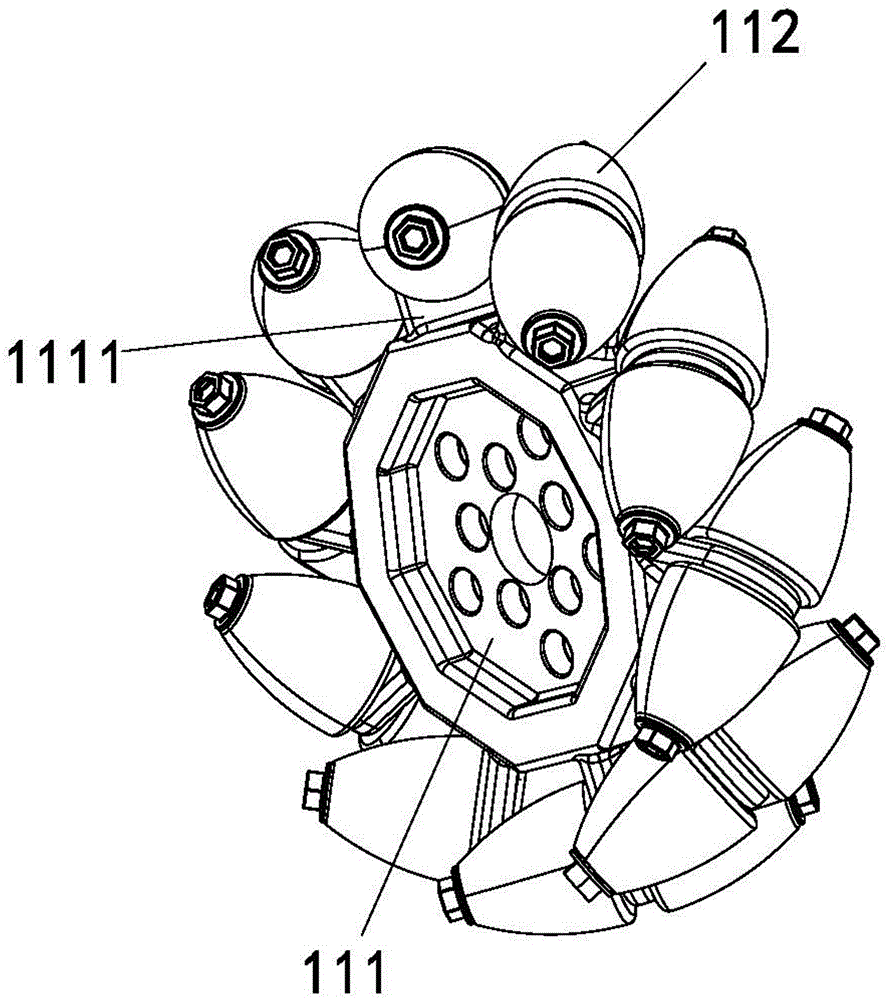
[0038] Embodiment 3: a kind of wheel group structure that is applicable to industrial vehicle running gear, as image 3 As shown, it includes a driving wheel 111 and a driven wheel 112; several hinged seats 1111 are arranged along the circumferential surface of the driving wheel 111, and the driven wheel 112 is rotatably connected to the hinged seats 1111, and the axis of the driven wheel 112 is inclined to the axis of the driving wheel 111 ; In order to improve the effective contact between the driven wheel 112 and the ground in various walking modes, the driven wheel 112 has a tapered outer diameter gradually decreasing along the direction from the middle to both ends.


PUM


Abstract

The invention relates to logistics equipment, in particular to an industrial vehicle and a traveling mechanism thereof. Through the technical scheme, the traveling mechanism of the industrial vehicle at least comprises four wheel sets, and closed-loop connecting lines of the four wheel sets are in the shape of a quadrangle; the four wheel sets are the same in structures, and each wheel set comprises a driving wheel and a plurality of driven wheels which can be driven by a friction force generated between the driven wheels and a traveling medium to rotate and are distributed along the peripheral direction of the driving wheel; the axes of the driven wheels in the same wheel set are inclined to the axis of the corresponding driving wheel; the axes of any two driving wheels in the four wheel sets are in a superposed or parallel state; the axes of the driven wheels of the two wheel sets in opposite angle distribution in the four wheel sets are in a parallel or superposed state; the axes of the driven wheels of the two wheel sets positioned at the two ends of any side of the quadrangle respectively are in a crossed state. The traveling mechanism is simple in structure, and can be beneficial for realizing the multi-mode traveling mode of the industrial vehicle.

Description

technical field [0001] The invention relates to logistics equipment, in particular to an industrial vehicle and its traveling mechanism. Background technique [0002] Prior art, such as the driving mechanism of a rail-type truck disclosed in the invention patent application with the application publication number CN101700776A, is composed of a supporting frame unit, a driving unit and a follower unit, and the drive unit and the follower unit are composed of a support frame unit Connected, the upper and lower longitudinal beams of the support frame unit are respectively equipped with the drive unit support bearing and the follower unit support bearing, the upper and lower ends of the drive frame are respectively equipped with rotary shafts, 2 road wheels, 4 guide wheels, The follow-up installation frame and the track selection device with four guide wheels constitute a follow-up unit. The four guide wheels are respectively installed on the four corners of the drive installati...

Claims


Application Information

Patent Timeline
IPC IPC(8): B60B19/12B62D63/02
Inventor 宁勤方马贤祥周磊张舒原杨峰张剑
Owner ZHEJIANG DAMON TECH CO LTD
Learn More