
Oil reservoir collector

A technology for oil reservoirs and oil wells, applied in the field of oil reservoir collectors, can solve the problems of oil wells unable to maintain normal production, flow difficulties in low-temperature areas, and loss of fluidity, etc., to improve the effect of viscosity reduction, facilitate collection, and ensure efficiency and effectiveness Effect

Inactive Publication Date: 2015-08-12
ZHEJIANG SCI-TECH UNIV
View PDF6 Cites 2 Cited by
  • Summary
  • Abstract
  • Description
  • Claims
  • Application Information

AI Technical Summary

Problems solved by technology

[0003] However, the water depth of deep-water oil fields is generally between 500 and 2,500 meters. Due to factors such as its deep depth, a low-temperature area will be formed on the seabed. In addition, the temperature sensitivity of heavy oil and its own high viscosity, so in the low-temperature area. Difficulty flowing, or even gradually losing fluidity, so that the oil well cannot maintain normal production

Method used


Image

  • Oil reservoir collector
  • Oil reservoir collector
  • Oil reservoir collector

Examples


Embodiment Construction

[0025] The present invention will be further described below in conjunction with the accompanying drawings and specific embodiments.

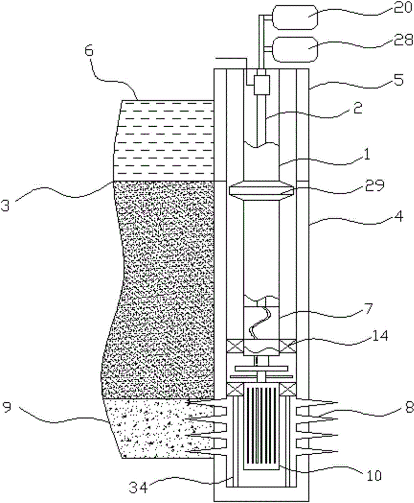
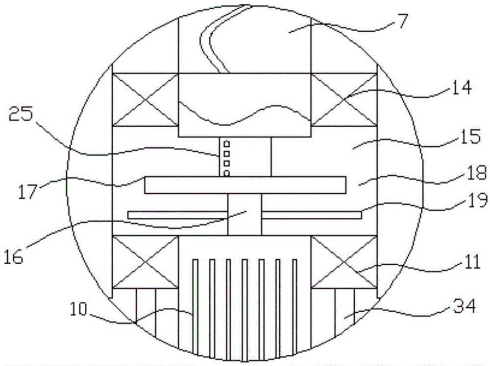
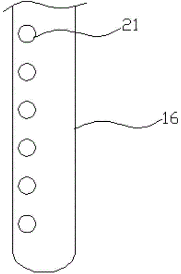
[0026] like figure 1 , figure 2 , image 3 , Figure 4 , Figure 5 , Figure 6 , Figure 7 In the shown embodiment, an oil reservoir recovery device comprises a main tubing 1, a hollow sucker rod 2 with an open upper end, and an oil wellbore 4 extending below the seabed mud line 3, and the oil wellbore is provided with There is a riser 5 with an inner cavity, the top of the riser protrudes from the sea surface 6, the wall of the oil wellbore and the pipe wall of the riser are sealed and connected, the main oil pipe passes through the inner cavity of the riser, and the lower end of the main oil pipe extends In the oil wellbore, the main oil pipe is provided with a screw pump 7, the upper end of the main working screw of the screw pump is connected with the lower end of the sucker rod, and the screw pump is located at the lower end of the ...


PUM


Abstract

The invention discloses an oil reservoir collector, and aims to provide an oil reservoir collector which can reduce the viscosity of heavy oil with high viscosity in the oil extraction process to improve the liquidity of heavy oil and guarantee smooth collection of heavy oil reservoir. The oil extraction device comprises a main oil pipe, a hollow sucker rod, and an oil wellbore. The oil wellbore is equipped with a riser. The lower end of the main oil pipe extends into the oil wellbore. The main oil pipe is internally equipped with a screw pump, and a main working screw of the screw pump is connected with the sucker rod. The lower part inside the oil wellbore is provided with a sand control screen, the sand control screen has a screen oil outlet in the top, and the oil outlet of the screen is communicated with the oil inlet of the screw pump. The sucker rod is internally provided with a cable of which one end is connected with a power supply. The oil reservoir collector has the following beneficial effects: heavy oil can be heated reasonably, so that the viscosity is reduced, and collection is facilitated; and carbon dioxide and water vapor can be fed in to reduce the viscosity of crude oil which is to rise or is rising.

Description

technical field [0001] The invention belongs to the technical field of oil reservoir exploitation, and in particular relates to an oil reservoir recovery device. Background technique [0002] Heavy oil reservoirs are widely distributed in the world. According to statistics, the geological reserves of heavy oil (including bitumen) reservoirs are at least four times that of proven conventional crude oil reserves, and even more than six times in optimistic estimates. With the exploration of deep water, deep water heavy oil has received more and more attention, and its exploitation and development activities have also been carried out all over the world. [0003] However, the water depth of deep-water oil fields is generally between 500 and 2,500 meters. Due to factors such as its deep depth, a low-temperature area will be formed on the seabed. In addition, the temperature sensitivity of heavy oil and its own high viscosity, so in the low-temperature area. The flow is difficult...

Claims


Application Information

Patent Timeline
Patent Type & Authority Applications(China)
IPC IPC(8): E21B43/24E21B43/16
CPCE21B43/24E21B43/164
Inventor 孙永剑万昌江刘东升
Owner ZHEJIANG SCI-TECH UNIV
Learn More