Fan control system and method based on Internet of Things

A fan control and Internet of Things technology, applied in pump control, non-variable pumps, machines/engines, etc., can solve the problems of reduced user comfort, energy waste, and unlaunched smart fan equipment, etc., to improve convenience Effect

Active Publication Date: 2015-08-12
ARCHITECTURAL DESIGN & RES INST OF SOUTH CHINA UNIV OF TECH
View PDF7 Cites 14 Cited by
  • Summary
  • Abstract
  • Description
  • Claims
  • Application Information

AI Technical Summary

Problems solved by technology

The open-loop control means that no feedback device and sensor module are added, that is, the real-time rotation speed of the fan motor is not collected and fed back, and the user cannot know the current speed of the fan, nor can it adjust the speed of the fan motor in real time through comparison and calculation;
[0005] 2. Traditional fans hardly have any microprocessors attached, so they do not have the functions of intelligent decision-making and self-organization
A fan device without an accompanying microprocessor cannot be an autonomous agent that operates and makes decisions;
[0006] 3. Traditional fans are generally not equipped with smart sensors, such as temperature sensors, humidity sensors, PM2.5 detectors, etc., so it is impossible to perceive and learn the status and information around the current operating environment of the fan
In the absence of environmental conditions, the fan cannot adjust its speed in a timely manner according to the actual situation and needs, which may lead to a decrease in user comfort and waste of energy;
[0007] 4. At present, there is hardly any smart fan equipment based on the concept and level of the Internet of Things on the market, that is, through the concept of networking, Internet of Things, and intelligence to coordinate, manage and control fan equipment

Method used


Image

  • Fan control system and method based on Internet of Things
  • Fan control system and method based on Internet of Things
  • Fan control system and method based on Internet of Things

Examples


Embodiment Construction

[0036] The present invention will be further described in detail below in conjunction with the embodiments and the accompanying drawings, but the embodiments of the present invention are not limited thereto.

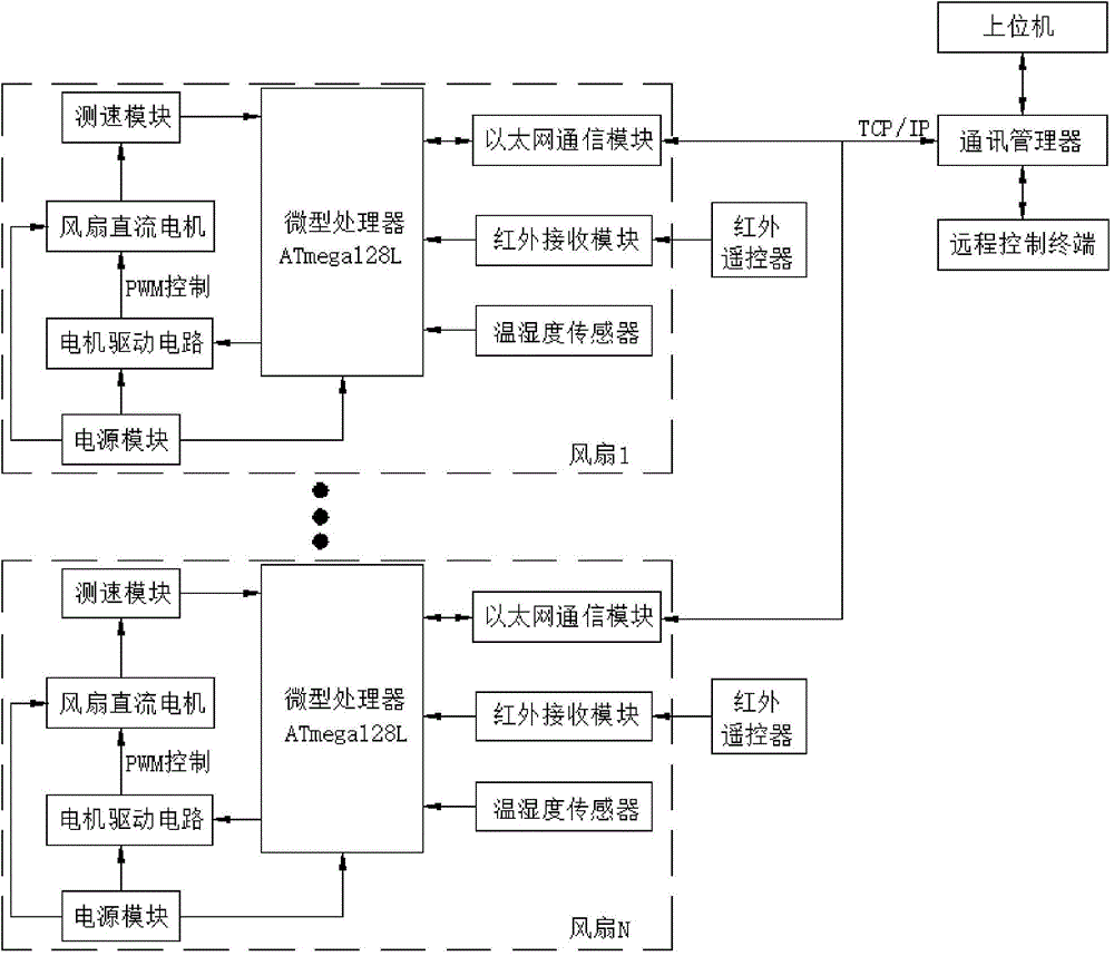
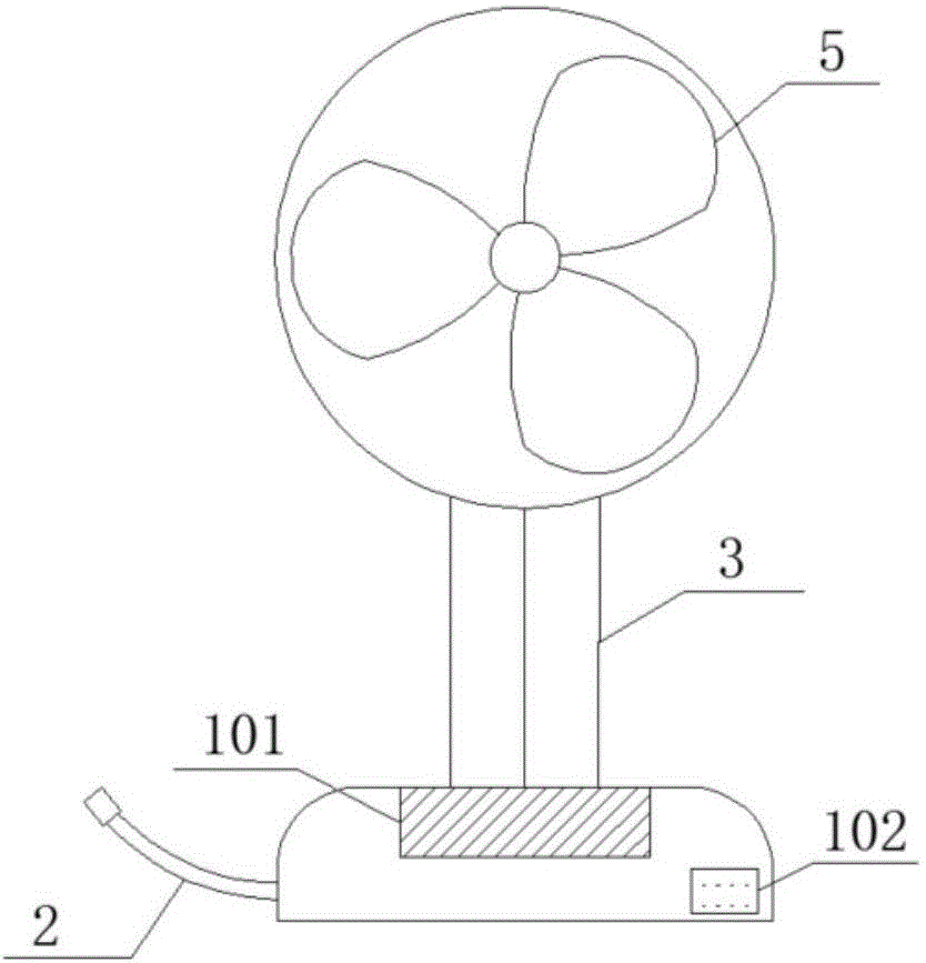
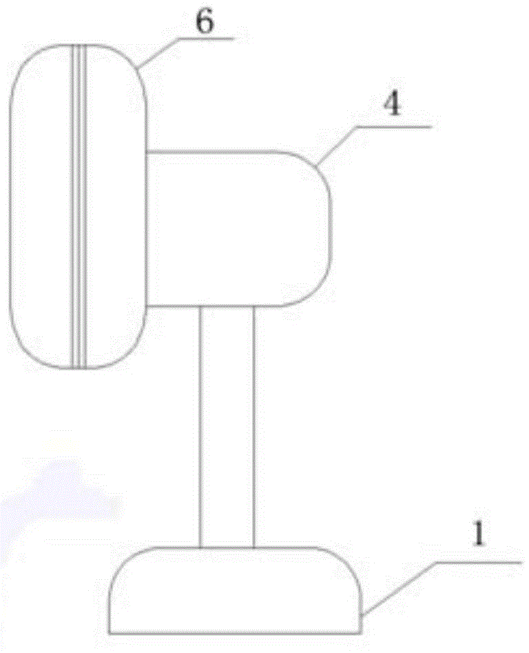
[0037] Such as figure 1 , 2 , 3. A fan control system based on the Internet of Things, including a microprocessor, and a motor drive module, a speed measurement module, an infrared receiving module, a temperature and humidity sensor connected to the microprocessor, and an infrared remote controller, a power supply module, The remote control terminal, wherein the motor drive module and the speed measurement module are respectively connected to the fan DC motor, the power supply module supplies power to the fan DC motor, the motor drive circuit and the microprocessor, and the remote control terminal is connected to more than one microprocessor.

[0038] The remote control terminal is connected with the microprocessor through the Ethernet communication module.

[0039] Th...


PUM


Abstract

The invention discloses a fan control system based on the Internet of Things. The fan control system comprises micro-processors, motor driving modules, speed test modules, infrared-receiving modules and temperature and humidity sensors. The motor driving modules, the speed test modules, the infrared-receiving modules and the temperature and humidity sensors are connected with the micro-processors. The fan control system further comprises infrared remote controllers, power modules and remote control terminals. The motor driving modules and the speed test modules are connected with fan direct-current motors. The power modules supply electricity to the fan direct-current motors, motor driving circuits and the micro-processors. A remote control terminal is connected with more than one micro-processor.The fan control system and the method based on the Internet of Things have following beneficial effects: on the basis of a conventional fan, the network communication function is added such that a networking function is obtained; and a conventional household electrical appliance is planned and managed by a networked way of thinking.

Description

technical field [0001] The invention relates to the field of smart home and networked control equipment, in particular to a fan control system and method based on the Internet of Things. Background technique [0002] The fan is a very common household appliance, especially in the scorching summer, the fan can become a sharp tool for every household to cool down and cool off the heat. Compared with air conditioners, fans have the characteristics of environmental protection, energy saving, low price and high cost performance, so they will still exist widely in the future. However, many of the existing and traditional fans are controlled locally, that is, through the fixed physical buttons on the fan or the on-site operation of the short-distance remote control, operations such as starting and stopping of the fan and speed regulation are realized, and the basic control method are relatively simple. Existing traditional fans seldom involve the concept of remote control, Intern...

Claims


Application Information

Patent Timeline
Patent Type & Authority Applications(China)
IPC IPC(8): F04D27/00
CPCF04D27/007
Inventor 耿望阳余辉荣陈乔敬何振勇李伟胜
Owner ARCHITECTURAL DESIGN & RES INST OF SOUTH CHINA UNIV OF TECH
Why Eureka
Try Eureka