Equipment arrangement structure provided with single-row induced draft fan behind dust catcher and flue gas system

A technology for equipment layout and induced draft fan, which is applied in the direction of lighting and heating equipment, waste gas exhaust device, combustion product treatment, etc. The direct and smooth connection of roads, the reduction of civil construction costs, and the effect of reasonable layout

Active Publication Date: 2015-08-12
CHINA ENERGY ENG GRP GUANGDONG ELECTRIC POWER DESIGN INST CO LTD
View PDF5 Cites 5 Cited by
  • Summary
  • Abstract
  • Description
  • Claims
  • Application Information

AI Technical Summary

Problems solved by technology

[0005] Based on this, aiming at the unreasonable layout of the above-mentioned traditional equipment after the dust collector, it is difficult to make full use of the space everywhere, so that the layout of the equipment after the dust collector occupies a large area, the flue is long, and the resistance is large. The equipment layout structure and flue gas system after the dust collector of the single-row induced draft fan

Method used


Image

  • Equipment arrangement structure provided with single-row induced draft fan behind dust catcher and flue gas system
  • Equipment arrangement structure provided with single-row induced draft fan behind dust catcher and flue gas system
  • Equipment arrangement structure provided with single-row induced draft fan behind dust catcher and flue gas system

Examples


Embodiment Construction

[0028] Embodiments of the present invention will be described in detail below in conjunction with the accompanying drawings.

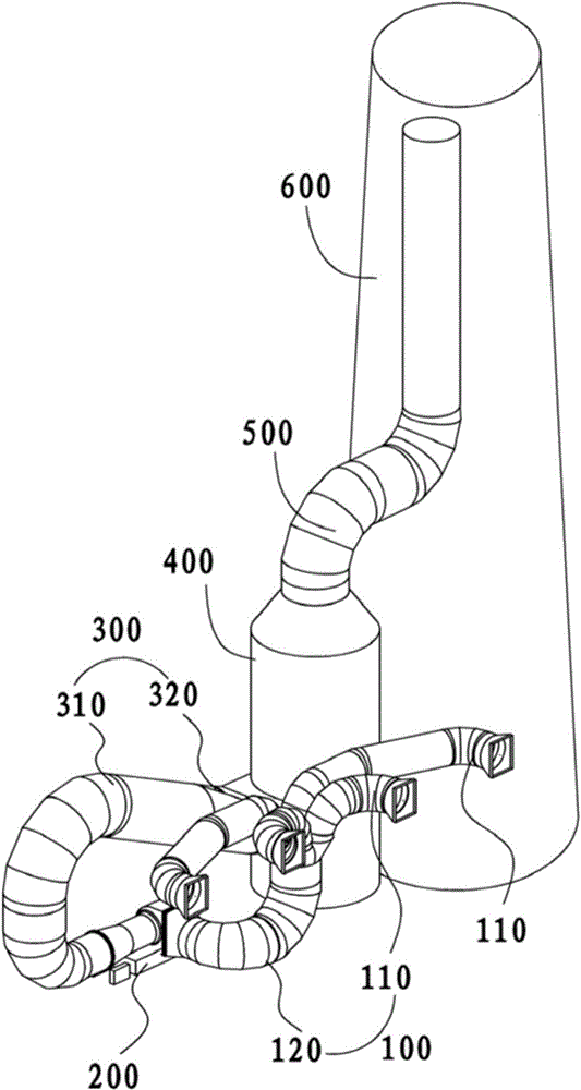
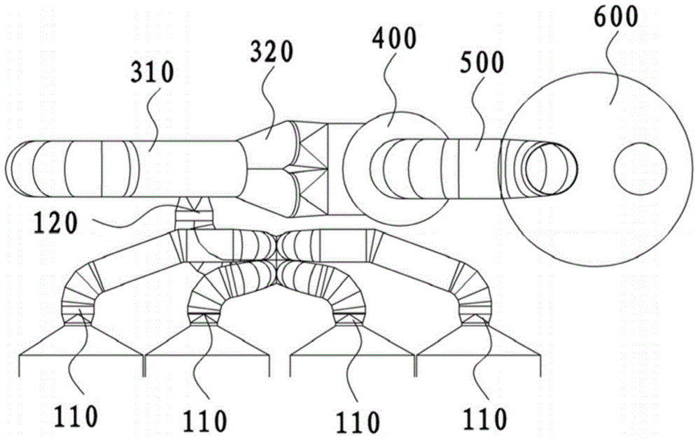
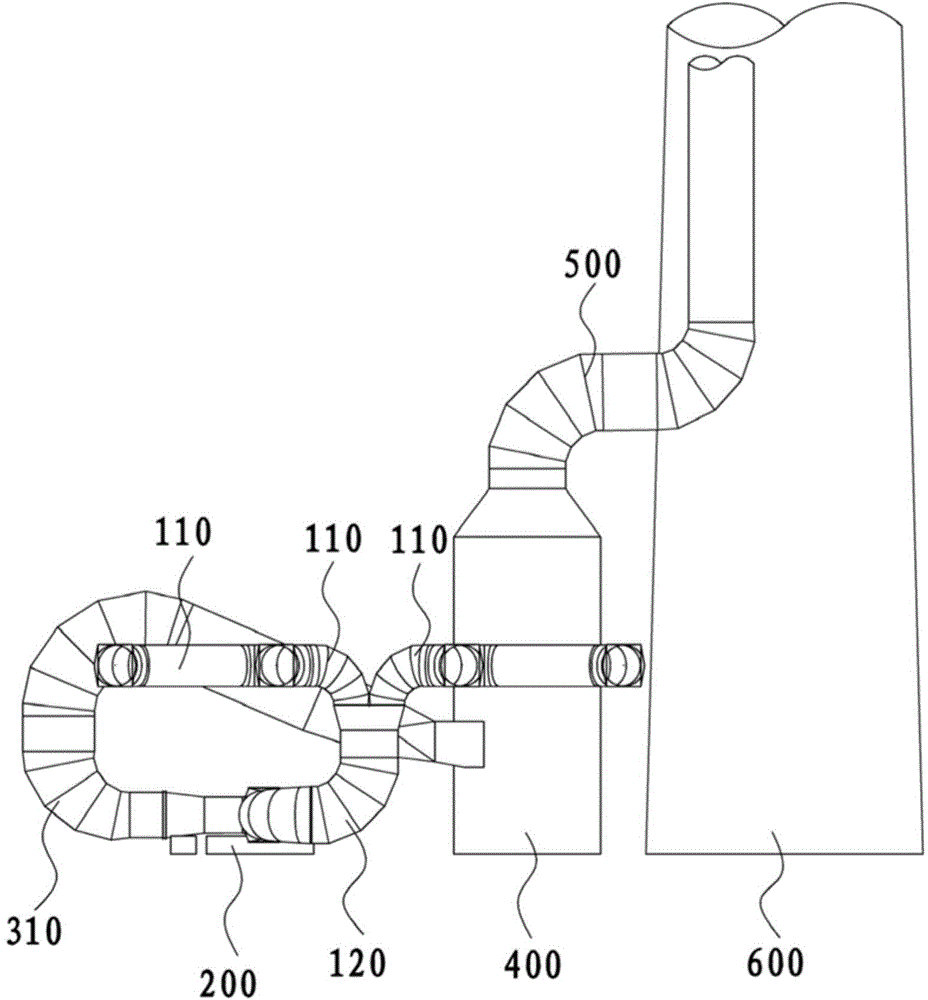
[0029] like figure 1As shown, a device arrangement structure behind the dust collector equipped with a single-row induced draft fan (that is, the arrangement structure of various equipment arranged behind the dust collector), including a single-row induced draft fan 200 connected sequentially through a cylindrical flue, a desulfurization absorption The tower 400, the chimney 600, and the center lines of the single row induced draft fan 200, the desulfurization absorption tower 400, and the chimney 600 are all located on the same plane. That is, the projections on the same plane of the above-mentioned devices arranged in the three-dimensional space are all located on a straight line. After the dust collector, the single row induced draft fan 200, the desulfurization absorption tower 400, the chimney 600 and other equipment are jointly arranged in a "on...


PUM


Abstract

The invention discloses an equipment arrangement structure provided with a single-row induced draft fan behind a dust catcher and a flue gas system. The equipment arrangement structure provided with a single-row induced draft fan behind the dust catcher comprises the single-row induced draft fan, a desulfurization absorption tower and a chimney, wherein the single-row induced draft fan, the desulfurization absorption tower and the chimney are successively connected by flues; the center lines of the single-row induced draft fan, the desulfurization absorption tower and the chimney are positioned on the same plane; the desulfurization absorption tower and the chimney are both vertically arranged; the single-row induced draft fan is laterally arranged on the outer side of the desulfurization absorption tower; the outlet of the single-row induced draft fan is back onto the desulfurization absorption tower; an outlet flue is connected by directly facing the inlet of the desulfurization absorption tower after slowly rotating. All pieces of equipment behind the dust catcher are subjected to spatial combined arrangement of a horizontal straight line shape, so that the arrangement among all pieces of equipment is more compact, occupied lands are reduced, the length of connection flues is reduced so as to save the materials of the flues, all pieces of equipment behind the dust catcher are reasonably arranged, and a stereo space behind the dust catcher is effectively utilized.

Description

technical field [0001] The invention relates to the technical field of thermal power generation, in particular to an equipment layout structure and a flue gas system after a dust collector equipped with a single-row induced draft fan. Background technique [0002] In a coal-fired thermal power plant project, the distance from the outlet of the dust collector to the center line of the chimney is one of the important land occupation indicators. Most of the equipment in the flue gas system is arranged behind the boiler, and the layout of the front flue and the dust collector is relatively fixed. The size of the equipment layout behind the dust collector and the flue cost account for a large proportion of the initial investment of the power plant, and the resistance of the flue also directly affects the operating economy of the power plant. [0003] The main layout pattern of the equipment behind the dust collector at home and abroad basically adopts the arrangement of each equi...

Claims


Application Information

Patent Timeline
Patent Type & Authority Applications(China)
IPC IPC(8): F23J15/02F23J13/00
Inventor 杨劲范旭潘灏郑赟李伟科马雪松黄涛张超昱
Owner CHINA ENERGY ENG GRP GUANGDONG ELECTRIC POWER DESIGN INST CO LTD
Why Eureka
Try Eureka