
Optical system for head mount display

An optical system and display technology, applied in optics, optical components, instruments, etc., can solve the problems of prolonged production time, cumbersome production, time-consuming, etc., and achieve the effects of reducing production costs, improving economic benefits, and minimizing size

Inactive Publication Date: 2015-08-12
GREEN OPTICS CO LTD +1
View PDF11 Cites 5 Cited by
  • Summary
  • Abstract
  • Description
  • Claims
  • Application Information

AI Technical Summary

Problems solved by technology

Therefore, in the case of an aspheric prism, not only is the production very cumbersome, but also more optical surfaces are used to improve the optical performance, so that the production cost of the optical components increases and there are many difficulties in the arrangement of the optical components.
[0006] In addition, according to the prior art, the assembly of the optical system itself is quite difficult due to the need to tilt the curved surface with respect to the viewpoint plane
Therefore, the more additional optical components are installed, the direct assembly cost will be incurred in addition to the processing cost, and the time required for assembly will be taken, so there is a disadvantage that the production time is also lengthened.
[0007] As an example, Japanese Laid-Open Patent Publication No. 2006-065234 (published on March 9, 2006) discloses a decentered optical system that uses only one optical component to form a virtual image at a viewpoint and an optical system using it. An optical system that uses only one optical component to form a virtual image at the viewpoint, but two reflections and two refractions are generated in one component, so the surfaces that bring about changes in refractive power are 3 surfaces in total (in 1 surface repeats reflection and refraction), therefore, there is a problem that it is very difficult to arrange each optical component
[0008] Similarly, in the image display device of Japanese Laid-Open Patent Publication No. 2006-313365 (published on November 16, 2006), there are as many as three surfaces that bring about changes in refractive power, and reflection is repeated on one surface. and refraction, therefore, the production cost of optical components needs to be very high, and it is difficult to arrange each optical component

Method used


Image

  • Optical system for head mount display
  • Optical system for head mount display
  • Optical system for head mount display

Examples


Embodiment Construction

[0044] Preferred embodiments of the present invention will be described in detail below with reference to the accompanying drawings. It should be noted that the same symbols in each figure indicate the same configuration wherever possible. In the following description, each specific specific matter appears, and it is provided in order to help a more comprehensive understanding of this invention. Moreover, in describing the present invention, when it is judged that the detailed description of related known functions or configurations may unnecessarily obscure the gist of the present invention, the detailed description will be omitted.

[0045]The present invention provides an optical system for HMD for a Head Mount Display (HMD) which has difficulty in manufacturing cost and arrangement of optical components due to the use of more optical surfaces in order to improve optical performance, Only one reflective mirror is used, thereby reducing the manufacturing cost and the diffic...


PUM


Abstract

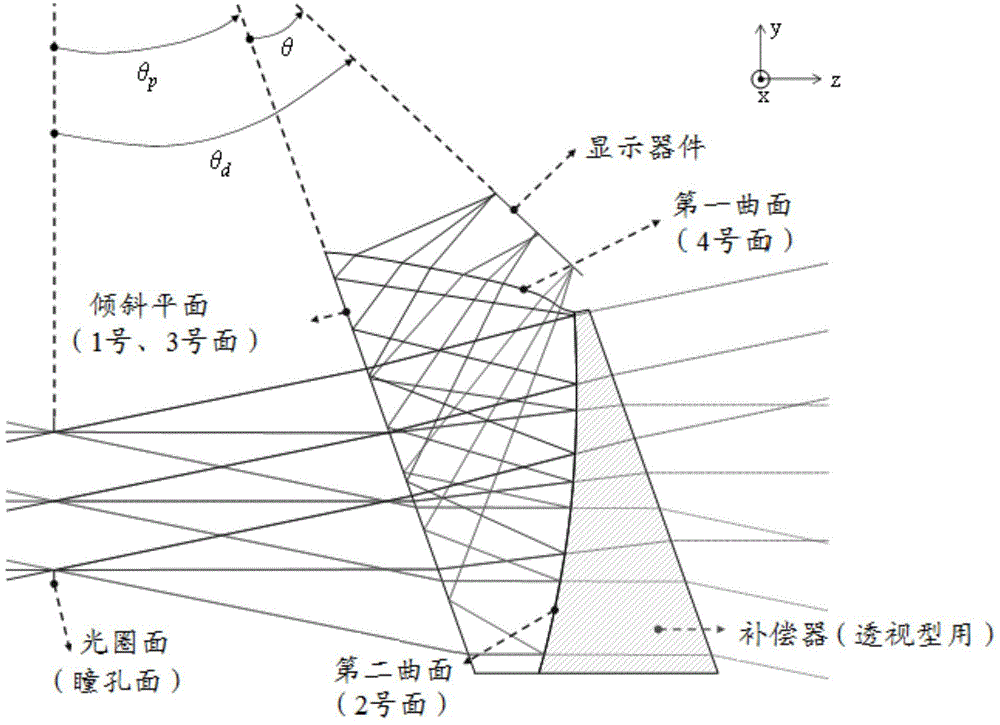
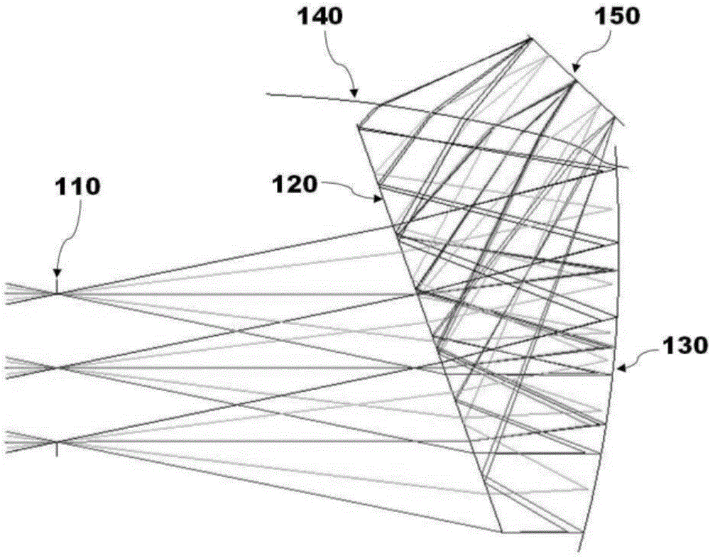
The invention especially relates to an optical system for head mount display, wherein the system forms a virtual image at a pupil position, enables an image of a small-size display to be amplified, and brings scene feeling and immersion feeling to a user. The system specifically achieves an aspheric surface Prism form, and the aspheric surface Prism enables light scattered by a small-size display device (such as a liquid crystal display (LCD) or a liquid crystal on silicon (LCoS) display) to be refracted on an eccentric first curved surface, and to be reflected on an inclined plane and a second curved surface. Moreover, a virtual image is formed through the refraction of the inclined plane. Because the system just employs one reflector mirror, the system can reduce the manufacture cost and the arrangement difficulty of the reflection surface. The mirror machining is just carried out for one time, so the system can improve the economic benefit of machining, and a proper compensator is machined for jointing, thereby specifically achieving a small-size and light perspective-type head-mount display.

Description

technical field [0001] The present invention relates to a head-mounted display device, and in particular to an optical system for a head-mounted display that forms a virtual image at the pupil position to enlarge the image of a small display, thereby giving the user a sense of presence and immersion. Head Mount Display). Background technique [0002] Generally speaking, a head-mounted display device (Head Mount Display, HMD) is an image display device that uses sophisticated optical devices to enable the image light generated at a position very close to the eyes to form a virtual image at a distance. The focal point is formed in the form of a large picture, so that the user can observe a magnified virtual image. HMD is divided into closed (See-close) type and see-through (See-through) type. The closed (See-close) type head-mounted display device cannot observe the surrounding environment and can only observe the image divergent from the display device. The see-through head...

Claims


Application Information

Patent Timeline
Patent Type & Authority Applications(China)
IPC IPC(8): G02B27/01G02B17/08
CPCG02B27/0172G02B17/0816G02B17/0832G02B17/086G02B2027/0178
Inventor 刘载名李基勋景宰玄
Owner GREEN OPTICS CO LTD
Learn More