CPU (central processing unit) integrated heating pipe radiator structure

A technology that integrates heat pipes and radiators, applied in the fields of instruments, electrical digital data processing, digital data processing components, etc., can solve the problems of low contact surface between heat pipes and heat sources, limited cooling performance of radiators, and low return efficiency of heat pipes, etc. Achieve the effect of being suitable for large-scale promotion, reducing the possibility of capillary limit occurrence, and increasing the difficulty of the process

Inactive Publication Date: 2015-08-12
TIANJIN HUAIDA TECH
View PDF0 Cites 4 Cited by
  • Summary
  • Abstract
  • Description
  • Claims
  • Application Information

AI Technical Summary

Problems solved by technology

However, with the development of computers towards compactness, the cooling performance of the radiator is limited, and the current aluminum extrusion radiator has reached the limit of heat transfer
Therefore, heat pipes known as superconductors have been paid attention to in the field of electronic cooling. At present, conventional heat pipe radiators embed one or more circular heat pipes on the bottom heat dissipation copper block in contact with the CPU, and the heat is transferred to the heat sink through the heat pipes. The cooling end covered by fins dissipates heat through the heat sink, but the return efficiency of the heat pipe is not high, the cost is high, and the contact surface between the heat pipe and the heat source is not high, the heat dissipation efficiency is limited, and further improvement is needed

Method used


Image

  • CPU (central processing unit) integrated heating pipe radiator structure
  • CPU (central processing unit) integrated heating pipe radiator structure
  • CPU (central processing unit) integrated heating pipe radiator structure

Examples


Embodiment Construction

[0018] A specific embodiment of the present invention will be described below in conjunction with the accompanying drawings.

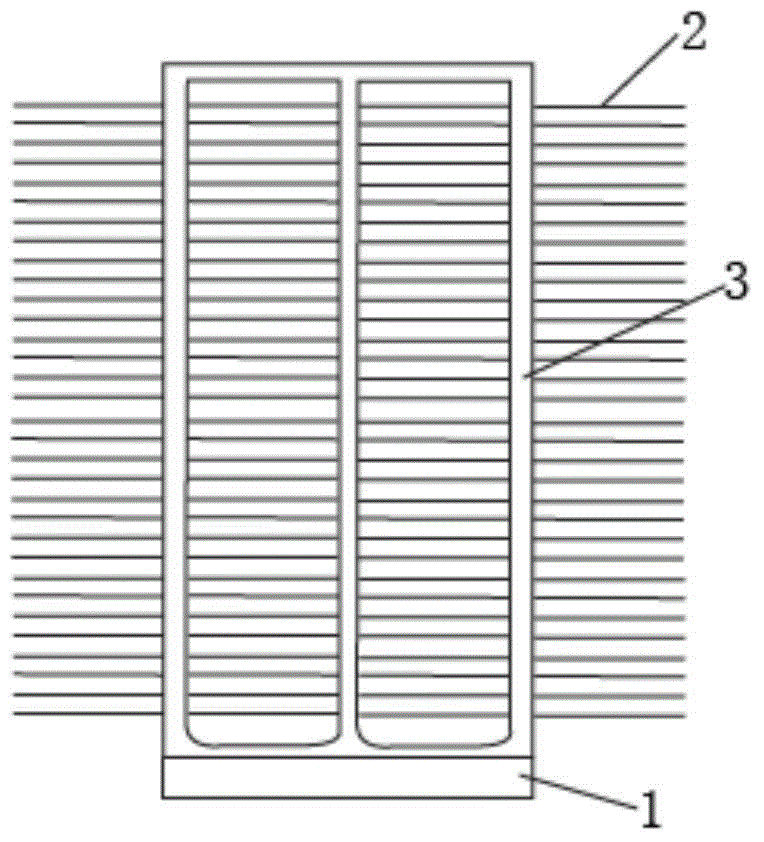
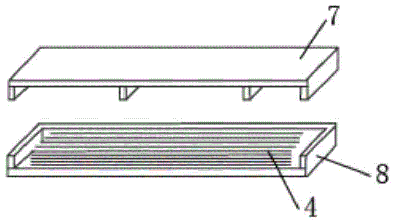
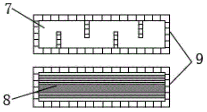
[0019] Such as figure 1 As shown, the present invention provides a CPU integrated heat pipe radiator structure, which is characterized in that it includes a flat plate evaporation heat pipe 1 and a rectangular cross-section condensation heat pipe 2. The bottom of the flat evaporating heat pipe 1 is in direct contact with the heat source, and the flat evaporating heat pipe 1 is provided with a fiber liquid-absorbing core structure 4 arranged in layers, and the inside of the rectangular cross-section heat pipe is provided with a through-hole support frame, which can enhance heat transfer. It can also prevent the heat pipe from being greatly deformed under internal pressure, external pressure or alternating pressure, thereby enhancing the strength of the heat pipe. The outside of the rectangular section heat pipe is equipped with heat dissipation fins 3,...


PUM


Abstract

The invention belongs to the technical field of computer radiation and particularly relates to a CPU (central processing unit) integrated heating pipe radiator structure. A rectangular cross-section condensation heating pipe is arranged above a flat plate evaporation heating pipe; the downside of the flat plate evaporation heating pipe is in direct contact with a heat source; fiber liquid absorbing core structures which are laminated are arranged in the flat plate evaporation heating pipe; a through hole supporting frame is arranged in the rectangular cross-section condensation heating pipe; radiating fins are arranged outside the rectangular cross-section condensation heating pipe and combine the flat plate evaporation heating pipe and the rectangular cross-section condensation heating pipe into a whole and communicate the flat plate evaporation heating pipe with the rectangular cross-section condensation heating pipe to form an inner passage type structure; the fiber liquid absorbing core structures are formed by arranging three cylindrical metal wires of which the circles are tangential to one another; a flowing passage is arranged between every two metal wires. The CPU integrated heating pipe radiator structure has the beneficial effects that due to the fact that the flat plate evaporation heating pipe is in direct contact with the heat source, the contact heat resistance is reduced, and the heat transfer power is high; a larger condensation area is obtained on the basis that steam is enabled to fully flow by the rectangular cross-section condensation heating pipe, and the heat transfer performance is high.

Description

technical field [0001] The invention belongs to the technical field of computer heat dissipation, and in particular relates to a CPU integrated heat pipe radiator structure. Background technique [0002] With the continuous improvement of the CPU integration and performance of personal computers, the power consumption of the CPU is increasing, and the heat flux on the surface of the CPU increases sharply, which reduces the performance and life of the chip, and affects the reliability of the system operation. At the same time, very high requirements have been put forward for the CPU cooling method, which has caused many changes in the cooling method. Traditional methods of cooling CPUs typically employ aluminum extruded heatsinks, which offer advantages in terms of unit cost, weight, and performance. However, as computers develop toward compactness, the cooling performance of radiators is limited. At present, aluminum extruded radiators have tended to the limit of heat trans...

Claims


Application Information

Patent Timeline
Patent Type & Authority Applications(China)
IPC IPC(8): G06F1/20
Inventor 刘建李力魏娜
Owner TIANJIN HUAIDA TECH
Why Eureka
Try Eureka