Imaging method for aerial camera, and system thereof

An aerial camera and image imaging technology, applied in image enhancement, image data processing, graphic image conversion, etc., can solve the problems of complex hardware equipment, poor real-time performance and reliability, etc., achieve wide viewing angle, high geometric accuracy, and improve reconnaissance efficiency. and real-time effects

Inactive Publication Date: 2015-08-12
CHANGCHUN INST OF OPTICS FINE MECHANICS & PHYSICS CHINESE ACAD OF SCI
View PDF3 Cites 38 Cited by
  • Summary
  • Abstract
  • Description
  • Claims
  • Application Information

AI Technical Summary

Problems solved by technology

[0006] The invention provides an image imaging method and system for aerial cameras to solve the technical problems of complex hardware, poor ...

Method used


Image

  • Imaging method for aerial camera, and system thereof
  • Imaging method for aerial camera, and system thereof
  • Imaging method for aerial camera, and system thereof

Examples


Embodiment Construction

[0074] The embodiments of the present invention will be described in detail below with reference to the accompanying drawings, but the present invention can be implemented in many different ways defined and covered by the claims.

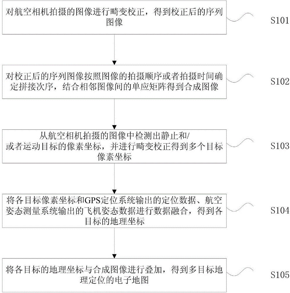
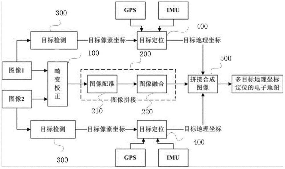
[0075] refer to figure 1 , the preferred embodiment of the present invention provides a kind of image forming method that is used for aerial camera, and aerial camera adopts the scanning imaging of monolithic array CCD sensor, and the image forming method of this embodiment comprises:

[0076] Step S101, performing distortion correction on the images captured by the aerial camera to obtain corrected sequence images;

[0077] In this embodiment, the distortion rate of the camera lens is measured by optical equipment, and the nonlinear distortion of the image generated by the lens is corrected according to the distortion rate to obtain the corrected aerial sequence image. The distortion rate of the camera lens is obtained by measuring the optical equ...


PUM


Abstract

The invention discloses an imaging method for an aerial camera, and a system thereof. The imaging method comprises the steps of performing distortion correction on the image which is photographed by the aerial camera for obtaining a sequence image after correction; determining splicing sequence on a corrected sequence image according to the photographing sequence or the photographing time of the image, utilizing a homography matrix between adjacent images for obtaining a synthetic image; detecting the pixel coordinate of a stationary object and/or moving object from an image which is photographed by the aerial camera, and performing distortion correction for obtaining a plurality of target pixel coordinates; performing data fusion on each target pixel coordinate, positioning data which are output from a GPS positioning system, and aircraft attitude data which are output of a flight attitude measuring system, thereby obtaining the geographical coordinate of each target; and superposing the geographical coordinate of each target with the synthetic image for obtaining an electronic map which is geographically positioned by multiple targets.

Description

technical field [0001] The invention relates to the fields of machine vision and image processing, in particular to an image imaging method and system for an area array CCD aerial camera. Background technique [0002] Resolution and field of view are the key technical indicators of aerial cameras. Due to the mutual restriction between field of view and resolution, and limited by the level of material technology, it is difficult for a single-chip area array CCD sensor to simultaneously meet the requirements of high resolution and high resolution for aerial reconnaissance missions. The requirements of large field of view, in order to meet the requirements of large field of view, high resolution, and high real-time performance of aerial reconnaissance missions, aerial cameras mostly use single-chip area array CCD sensor scanning imaging mode, through CCD sensor and special mechanical structure, at different times 1. Photograph and image the ground from different angles, and the...

Claims


Application Information

Patent Timeline
IPC IPC(8): G06T3/40G06T5/00
Inventor 刘晶红周前飞
Owner CHANGCHUN INST OF OPTICS FINE MECHANICS & PHYSICS CHINESE ACAD OF SCI
Why Eureka
Try Eureka