Manufacturing process of porous component and porous component

A technology for porous components and components, which is used in the field of manufacturing porous components and components, and can solve problems such as distortion and part size deviation

Active Publication Date: 2015-08-12
EMPRESA BRASILEIRA DE COMPRESSORES SA (EMBRACO)
View PDF8 Cites 9 Cited by
  • Summary
  • Abstract
  • Description
  • Claims
  • Application Information

AI Technical Summary

Problems solved by technology

On the other hand, sintering at high temperature after the injection molding of the part produces a strong volume shrinkage that can lead to dimensional deviations and distortions of the final part

Method used


Image

  • Manufacturing process of porous component and porous component
  • Manufacturing process of porous component and porous component
  • Manufacturing process of porous component and porous component

Examples


Embodiment Construction

[0026] In the present invention, the method used to manufacture the porous material is Powder Injection Molding (PIM), which is a deformation technique of powder metallurgy, and is modified in the invention herein so that It is possible to obtain a porous structure with the characteristics necessary for the specific intended application; in other words, for seeking a homogeneously distributed porous part of the gaseous fluid (flow restrictor) of the aerostatic bearing.

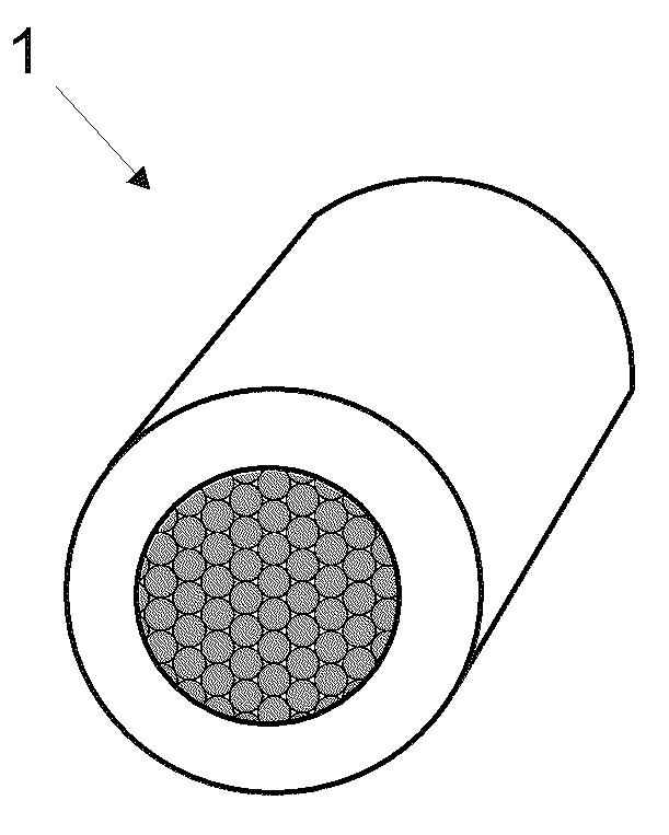
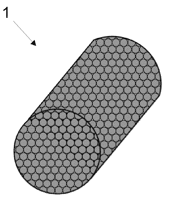
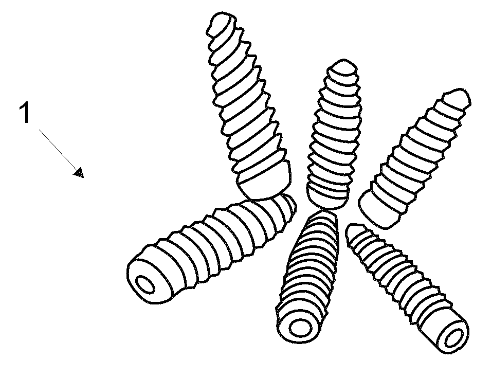
[0027] One such application concerns the aerostatic bearings of compressors, where the bearings of the compressors are realized by a layer of gas that balances the linear motion of the piston inside the cylinder. In order to do this, the amount of gas used to support the piston needs to be constant, so as to control the fluid flow, it is necessary to use a porous part 1 with a homogeneous porous structure that not only allows regulation of the flow but is evenly distributed in the system to be undertaken. The ...


PUM


Abstract

This invention refers to a process for manufacturing a porous component (1) to be used as flow restrictor, whose basic foundations include the metal injection molding process, which has been enhanced in order to obtain a component with open porosity homogeneously distributed. Such flow restrictor comprises at least one porous component (1), having at least one restricting portion with some porosity dimensioned to regulate the flow of gas that flows to an aerostatic bearing of a mechanical system, such as a hermetic compressor comprised by a piston at motion in relation to a cylinder, for instance. This invention also refers to the use and production of a porous component (1) obtained by powder injection molding or powder injection molding of multi-material parts, the porous component being (1) a flow restrictor with a layer of dense material; that is, with no open pores, on the outer surface parallel to the flow direction in which the flow through the porous component (1) shall occur, allowing it to be inserted into the bearing system without interfering with the porous structure of the core (dual porosity). The invention also refers to the sealing existing between the porous component (1) and its housing.

Description

[0001] The present invention relates to an improved method of powder injection molding (MIM) to obtain porous parts intended to limit and control the flow distribution of gaseous fluids in aerostatic bearings of mechanical systems such as hermetic compressors. Background technique [0002] Currently, the use of piston and cylinder sets driven by electric motors is very common in gas compressors for cooling equipment such as refrigerators, freezers and air conditioners for domestic, commercial and industrial use. In such gas compressors, the technical challenge observed is to ensure that the piston and cylinder are not in direct contact. Therefore, due to the relative movement between the piston and the cylinder, it is necessary to support the piston by means of the fluid between the movable surfaces of the piston-cylinder group in order to avoid contact between the movable parts and their premature wear. [0003] Often, for aerostatic bearings to work effectively, it is necess...

Claims


Application Information

Patent Timeline
Patent Type & Authority Applications(China)
IPC IPC(8): B22F3/22B22F7/00B22F3/11C22C1/08
Inventor F.威特斯托雷斯R.宾德A.N.克莱恩C.宾德R.穆勒施罗伊德K.帕格南富兰
Owner EMPRESA BRASILEIRA DE COMPRESSORES SA (EMBRACO)
Why Eureka
Try Eureka