
Method for improving liquidity of viscoelastic fluid via high frequency ultrasounds

A high-frequency ultrasonic and viscoelastic technology, applied in chemical instruments and methods, semiconductor/solid-state device manufacturing, shaking/oscillating/vibrating mixers, etc., can solve the problem of reducing fluid viscoelasticity and irreversible changes in the chemical properties of viscoelastic fluids , high cost and other issues, to achieve the effect of maintaining fluid stability

Inactive Publication Date: 2015-08-19
GUANGDONG UNIV OF TECH
View PDF4 Cites 1 Cited by
  • Summary
  • Abstract
  • Description
  • Claims
  • Application Information

AI Technical Summary

Problems solved by technology

Modification of the fluid after adding a diluent can significantly reduce the viscoelasticity of the fluid, but the chemical properties of the viscoelastic fluid also undergo irreversible changes, which may introduce other reliability problems, and it is even difficult to achieve high viscoelasticity. Effect of blocking air and protecting interconnection channels
In addition, the research and development of new diluents involves the intersection of multiple disciplines such as materials, physical chemistry and mechanics, and the research and development cycle is long and costly.
The viscoelasticity of the viscoelastic fluid can be effectively reduced by heating, but the high temperature potting fluid will cause uneven deformation and residual stress of the chip, thus affecting the reliability of the chip
[0004] To sum up, there is currently no effective solution for the high viscoelastic viscoelastic fluid potting needs in electronic products

Method used


Image

  • Method for improving liquidity of viscoelastic fluid via high frequency ultrasounds
  • Method for improving liquidity of viscoelastic fluid via high frequency ultrasounds
  • Method for improving liquidity of viscoelastic fluid via high frequency ultrasounds

Examples


Embodiment Construction

[0022] The present invention will be further described below in conjunction with the accompanying drawings and embodiments.

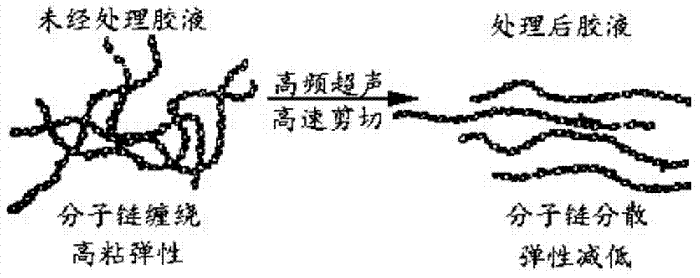
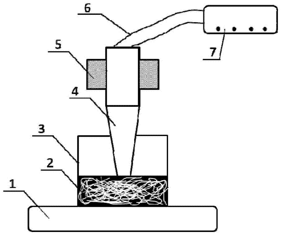
[0023] A method for improving the fluidity of viscoelastic fluid through high-frequency ultrasound, using an ultrasonic horn powered by an ultrasonic power supply, introducing high-frequency ultrasonic waves into the viscoelastic fluid to generate a large number of bubbles, and the shear motion generated by the ultrasonic horn Detonate the bubbles to break up the entangled molecular chains, reduce the viscoelasticity of the viscoelastic fluid, and improve the fluidity of the viscoelastic fluid.

[0024] The working frequency of the ultrasonic horn is 3000-200000Hz, and the power is 1-100W.

[0025] The vibration time of the ultrasonic horn in the viscoelastic fluid is 1-60 minutes.

[0026] The vibration time of the ultrasonic horn in the viscoelastic fluid is 5-8 minutes.

[0027] The viscoelasticity in viscoelastic fluids is mainly determined by the...


PUM


Abstract

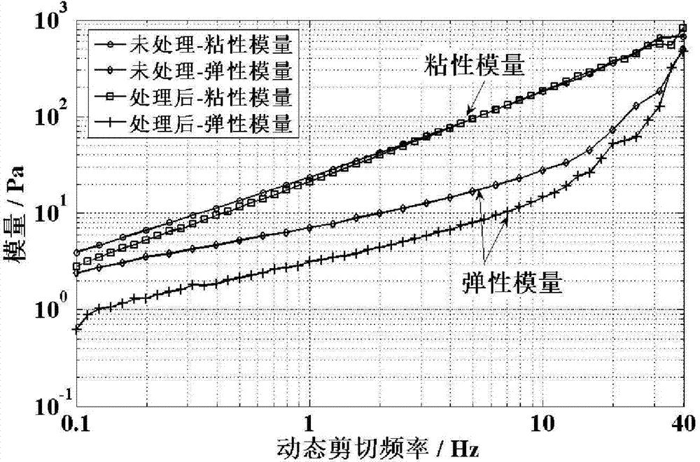
The present invention discloses a method for improving the liquidity of a viscoelastic fluid via high frequency ultrasounds. High frequency ultrasonic waves are introduced into the viscoelastic fluid by utilizing an ultrasound amplitude-change pole supplied with power by an ultrasonic power supply to generate a large amount of bubbles, and the bubbles are detonated by shear movement generated by the ultrasonic amplitude-change pole, so that molecular chains wound together are scattered, the viscoelasticity of the viscoelastic fluid is lowered, and the fluidity of the viscoelastic fluid is improved. The method lowers the viscoelasticity of the fluid by way of scattering the molecular chains wound together, but does not change the molecular structure, therefore, the chemical property of the fluid is not changed; Scattered molecular chains can be recovered in the winding state along with Brownian motion step by step after being poured, so that the high viscoelasticity of the viscoelastic fluid can be recovered, and connected channels are better protected. The method lowers the viscoelasticity of the viscoelastic fluid on the basis of the high frequency ultrasonic shear movement without high temperature, as a result, extra thermal stress and transformation are not introduced into a chip in a pouring process.

Description

technical field [0001] The invention belongs to the technical field of electronic packaging, and relates to a method for improving the fluidity of viscoelastic fluid through high-frequency ultrasound. Background technique [0002] After the chip is interconnected, it needs to be potted with a highly viscoelastic viscoelastic fluid, so that the electrical interconnection channel of the chip is isolated from the air and protected. During the potting process, because the viscoelasticity of the viscoelastic fluid is too large, the fluidity of the viscoelastic fluid is poor and the elasticity is strong, and it is difficult to be extruded or sprayed out, thus causing difficulty in potting. Especially when the jet dispensing technology is used for potting, excessive viscoelasticity of the viscoelastic fluid will cause the viscoelastic fluid to accumulate in the nozzle, which will not only affect the consistency of the potting quality, but even cause nozzle blockage in severe cases....

Claims


Application Information

Patent Timeline
Patent Type & Authority Applications(China)
IPC IPC(8): B01F11/02B01J19/10H01L21/56
Inventor 陈云高健陈新
Owner GUANGDONG UNIV OF TECH
Learn More