Driving system of shield tunneling machine and shield tunneling machine comprising driving system

A drive system and shield machine technology, applied in mining equipment, earthwork drilling, tunnels, etc., can solve the problems of high drive power of the cutter head, limited escape torque, and small escape torque, so as to improve drive efficiency and enhance drive efficiency , The effect of enhancing the ability to escape from difficulties

Inactive Publication Date: 2015-08-19
CHINA RAILWAY CONSTR HEAVY IND
View PDF4 Cites 3 Cited by
  • Summary
  • Abstract
  • Description
  • Claims
  • Application Information

AI Technical Summary

Problems solved by technology

The driving power of the cutter head is very large, and the driving efficiency of the hydraulic motor is low. If a single hydraulic motor is used for driving, the power loss is very large and the heat is serious. Therefore, the hydraulic motor drive is only used as an auxiliary driving method for the two-speed motor drive.
[0006] Usually, the drive system of the cutter head in the shield machine mainly includes two-speed motor main drive + hydraulic motor auxiliary drive and variable frequency motor drive. The former has the following defects: continuous speed regulation, poor geological adaptability, complex transmission mechanism, and failure rate High, affecting the excavation speed, the hydraulic motor and the motor cannot be driven at the same time; the latter is the main driving mode in the prior art, although the variable frequency motor can output a large torque at low speed, but is limited by the maximum electromagnetic torque, It has limited breakaway torque
In fact, the only way to increase the power of the motor is to increase the breakaway torque, which will inevitably lead to a significant increase in the installed power of the variable frequency motor
However, under high-speed excavation conditions, the motor torque is very small relative to the escape torque, which leads to waste of installed power of the motor

Method used


Image

  • Driving system of shield tunneling machine and shield tunneling machine comprising driving system
  • Driving system of shield tunneling machine and shield tunneling machine comprising driving system
  • Driving system of shield tunneling machine and shield tunneling machine comprising driving system

Examples


Embodiment 1

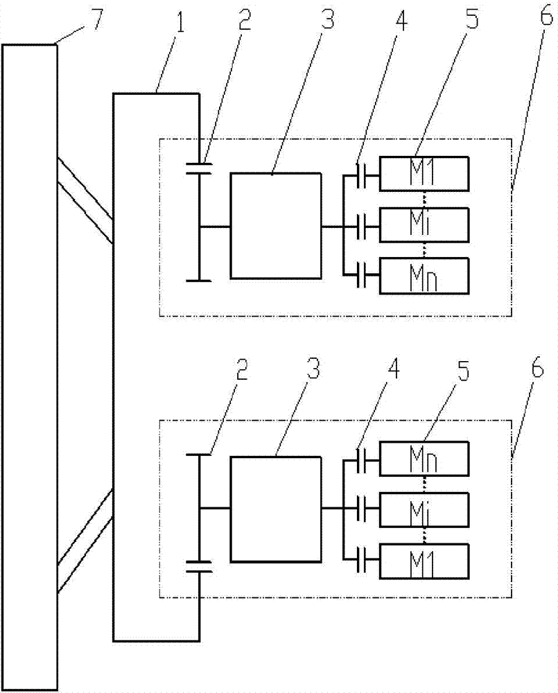
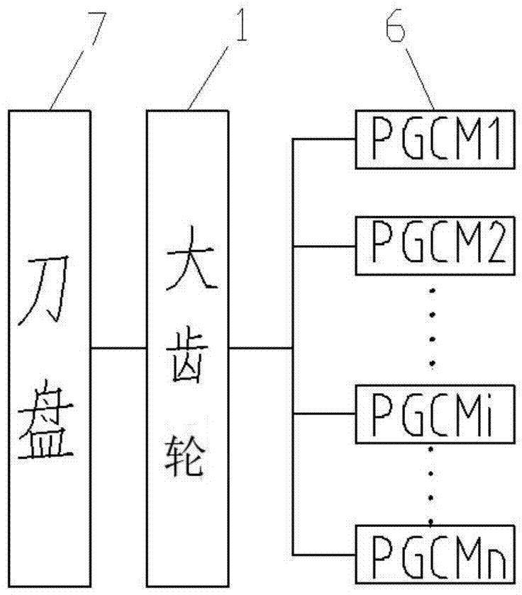
[0032] A drive system for a shield machine cutter head, see figure 1 , specifically including a large gear 1 arranged on the cutter head 7 and a drive unit 6 connected with the large gear 1 .

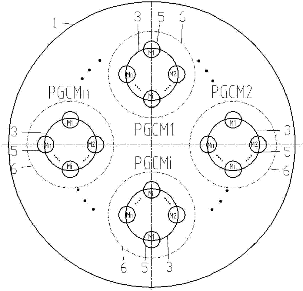
[0033] The number of the drive units 6 is n, and the value of n can be 1, or 2, or other numbers of more than 2, and the specific number can be selected according to actual needs. When the value of n is greater than or equal to 2, the drive units 6 are connected in parallel (connected in parallel with each other) and are uniformly arranged in a ring with the center of the cutterhead as the center (see image 3 ), which is conducive to the symmetrical distribution of the power output by the driving source on the large gear, which is beneficial to the force balance of the large gear, and improves the driving characteristics and service life of the ring gear; the combination of multiple drive units can be used simultaneously or partially. The advantages of easy installation, improved driv...

Embodiment 2

[0043] A shield machine, comprising a cutter head and the drive system of the shield machine cutter head as described in Embodiment 1 connected to the cutter head, the shield machine adopts such a drive system, so that the shield machine has geological adaptability Strong, high utilization rate of installed power, large torque, easy installation, and strong practicability.


PUM


Abstract

The invention firstly aims to provide a driving system of a shield tunneling machine. The driving system comprises a big gear and a driving unit connected with the big gear or at least two driving units which are connected in parallel and arranged in an annular mode by taking the center of a cutter as a circle center, and the big gear and the driving units are arranged on the cutter. Each driving unit comprises a small gear, a sped reducer and a power driving component, wherein the small gear is meshed with the big gear, an output shaft of the speed reducer is connected with the small gear, and an output shaft of the power driving component is connected with an input shaft of the speed reducer through a clutch device. The driving system of the cutter of the shield tunneling machine has the characteristics of high geology adaptability, high installed power utilization ratio, large torque and convenient installation. A second purpose of the invention lies in providing a shield tunneling machine comprising the driving system, thereby enabling the shield tunneling machine to meet practical requirements and be high in practicability.

Description

technical field [0001] The invention relates to the field of shield machine devices, in particular to a drive system for a shield machine cutter head and a shield machine including the drive system. Background technique [0002] Shield machine is an important construction machine in shield construction. Because shield construction has the advantages of safety, reliability, small environmental impact, low labor intensity, less earthwork, and high efficiency, it is widely used in urban rail, water conservancy, municipal engineering, mines, and highways. , Railway tunnels and other fields have been widely used. Because the shield machine is often constructed in complex and harsh working environments, its transmission system must be able to withstand heavy loads and large impacts, and is required to have functions such as high power, low speed and high torque output. [0003] Since the cutter head drive system is a key component of the shield machine, it has an important impact...

Claims


Application Information

Patent Timeline
IPC IPC(8): E21D9/08
CPCE21D9/08
Inventor 刘飞香程永亮彭正阳刘华徐震刘派
Owner CHINA RAILWAY CONSTR HEAVY IND
Why Eureka
Try Eureka