
Engine oil filtration device, engine lubrication system and vehicle

An oil filtration and engine technology, which is applied in the direction of engine lubrication, machine/engine, engine components, etc., can solve the problems of excessive cleanliness of the oil filtration device, unfavorable compact design of the engine, high processing and manufacturing costs, and achieve improved filtration. Effect, simple manufacturing process, low cost effect

Inactive Publication Date: 2015-08-19
BEIQI FOTON MOTOR CO LTD
View PDF7 Cites 3 Cited by
  • Summary
  • Abstract
  • Description
  • Claims
  • Application Information

AI Technical Summary

Problems solved by technology

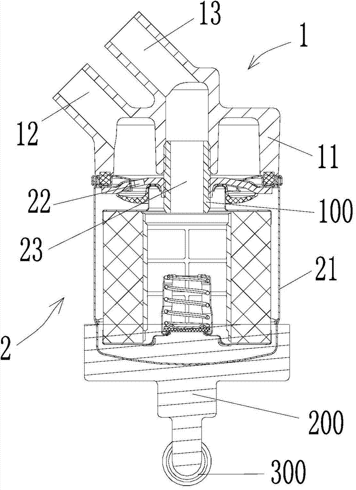
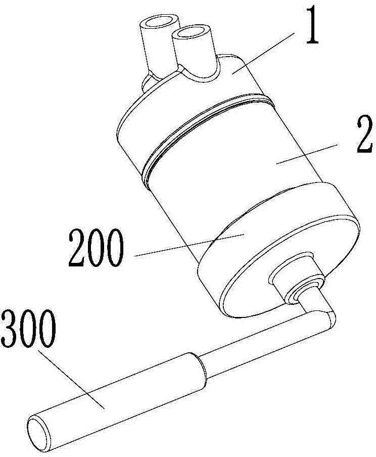
[0005] There are at least the following problems in the above-mentioned scheme: first, the screw sleeve 100 needs to be provided, and the internal thread needs to be processed on the support oil outlet pipe 13 and the filter oil outlet pipe 23, so the manufacturing cost is high, and the metal shavings generated during processing are easy Cause the cleanliness of the oil filter device to exceed the standard; second, if image 3 As shown in , in the process of screwing the other end of the screw sleeve 100 into the filter oil outlet pipe 23, it is necessary to insert a tightening tool 200 at the bottom of the filter 2, and use a tightening wrench 300 to perform the tightening operation
Therefore, the assembly space required by the oil filter device in the axial and radial directions is large, which is not conducive to the compact design of the engine; third, during the tightening operation, the sealing ring and the sealing surface of the connecting bracket 1 continue to contact and rub , it is easy to form scratches on the sealing ring, causing the risk of oil leakage and even damage to the engine

Method used


Image

  • Engine oil filtration device, engine lubrication system and vehicle
  • Engine oil filtration device, engine lubrication system and vehicle
  • Engine oil filtration device, engine lubrication system and vehicle

Examples


Embodiment Construction

[0038] Specific embodiments of the present invention will be described in detail below in conjunction with the accompanying drawings. It should be understood that the specific embodiments described here are only used to illustrate and explain the present invention, and are not intended to limit the present invention.

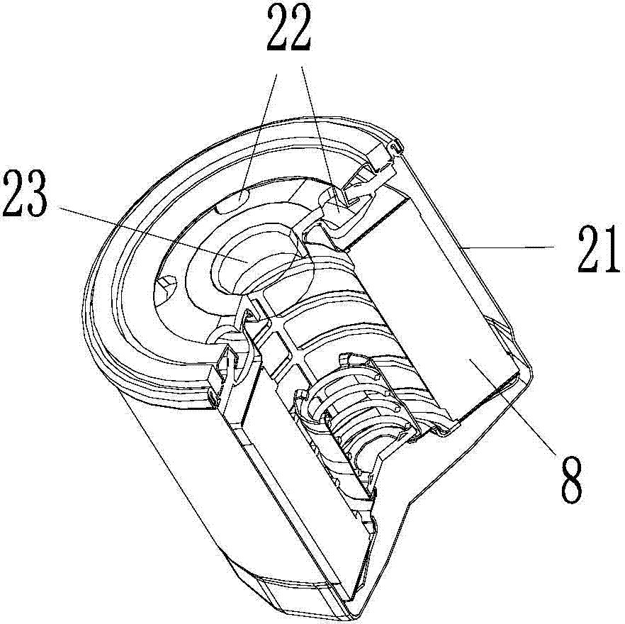
[0039] refer to Figure 4, The invention provides an oil filter device. The oil filter device includes a connecting bracket 1 and a filter 2 . The connecting bracket 1 includes a bracket housing 11 , and a bracket oil inlet pipe 12 and a bracket oil outlet pipe 13 are arranged in the bracket housing 11 . The filter 2 includes a filter housing 21 , and a filter oil inlet pipe 22 and a filter oil outlet pipe 23 are arranged in the filter housing 21 . The connection bracket 1 and the filter 2 are connected to each other through a bracket housing 11 and a filter housing 12 . And when the connecting bracket 1 and the filter 2 are connected to each other, the brac...


PUM


Abstract

The invention discloses an engine oil filtration device. The engine oil filtration device comprises a connecting bracket and a filter, wherein the connecting bracket comprises a bracket shell, and a bracket oil inlet pipe and a bracket oil outlet pipe arranged in the bracket shell; and the filter comprises a filter shell connected with the bracket shell, a filter oil inlet pipe arranged in the filter shell and connected with the bracket oil inlet pipe, and a filter oil outlet pipe arranged in the filter shell and connected with the bracket oil outlet pipe. The engine oil filtration device further comprises a buckle component for fixing the connecting bracket and the filter in an axial direction, a first sealing ring for sealing the bracket oil inlet pipe and the filter oil inlet pipe with respect to the bracket oil outlet pipe and the filter oil outlet pipe, and a second sealing ring arranged at the connected part of the bracket shell and the filter shell. The invention further discloses an engine lubrication system comprising the engine oil filtration device, and a vehicle comprising the engine lubrication system. The assembly operation of the engine oil filtration device can be simplified; and the engine structure is more compact.

Description

technical field [0001] The invention relates to the field of vehicles, in particular to an engine oil filter device, an engine lubricating system and a vehicle. Background technique [0002] The engine lubrication system involves a functional part—the oil filter device. This part is arranged between the outlet of the oil pump and the oil passage of the main oil passage, and is used to finely filter the impurities in the oil to ensure that the oil reaches a certain degree of cleanliness. The oil filter device has a filter element usually formed by folded filter paper inside, and the filter element satisfies a certain filtering area. Impurities (fibers, metal particles, etc.) with a certain particle diameter in the engine oil are blocked on the filter element during the filtration process, so as to achieve the purpose of cleaning the engine oil. After the impurities on the filter element of the oil filter have accumulated to a certain extent (certain weight), new filter comp...

Claims


Application Information

Patent Timeline
IPC IPC(8): F01M11/03F01M1/10
CPCF01M11/03F01M1/10
Inventor 武正兵蔡继春杨佳伟
Owner BEIQI FOTON MOTOR CO LTD
Learn More