Method of calculating maximum scour depth of rear part of debris flow drainage canal transverse sill and applications

A technology for scour depth and debris flow, applied in the direction of measuring devices, instruments, etc., can solve problems such as damage to the drainage channel project, increased construction costs, and difficulty in accurately determining the design burial depth of the rib sill

Inactive Publication Date: 2015-08-19
INST OF MOUNTAIN HAZARDS & ENVIRONMENT CHINESE ACADEMY OF SCI
View PDF5 Cites 13 Cited by
  • Summary
  • Abstract
  • Description
  • Claims
  • Application Information

AI Technical Summary

Problems solved by technology

According to the "Code for Design of Debris Flow Prevention and Control Engineering" (DZ / T0239-2004), the recommended value of the foundation buried depth of the anti-scour rib sill of the soft foundation energy dissipation type debris flow drainage channel is 1.5-4.0m, and the maximum buried depth is the minimum buried depth value In this case, it is difficult to accurately determine the design burial depth of the rib sill when designing the rib sill of the row guide groove
If a small value is taken in the design, during the operation of the drainage channel project, the rear of the rib sill may be damaged due to the erosion of debris flow, which will lead to the destruction of the drainage channel project; if a large value is taken in the design, it will lead to construction failure. cost increase

Method used


Image

  • Method of calculating maximum scour depth of rear part of debris flow drainage canal transverse sill and applications
  • Method of calculating maximum scour depth of rear part of debris flow drainage canal transverse sill and applications
  • Method of calculating maximum scour depth of rear part of debris flow drainage canal transverse sill and applications

Examples


Embodiment 1

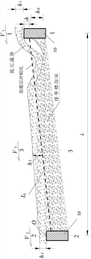
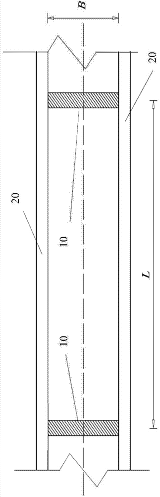
[0073] Such as figure 1 , figure 2 shown. A debris flow ditch is a medium-sized debris flow ditch with an altitude of 1920m to 3500m and a drainage area of ​​12.2km 2 . There have been many mudslides in the ditch, which seriously threatened the safety of local people's lives and properties. In order to reduce debris flow disasters, it is planned to build a drainage channel project on the debris flow accumulation fan. The debris flow drainage trough includes a number of groove bottom transverse penetrating rib sills 10 arranged at certain intervals and side walls 20 of the drainage trough on both sides. The total length of the drainage trough is 1 km. design, the steps are as follows:

[0074] The first step is to determine the vertical slope I of the design of the row guide groove through the measurement and calculation of the large-scale topographic map 0 It is 0.10; through field investigation and combined with the actual situation of the project, it is determined tha...

Embodiment 2

[0082] Such as figure 1 , figure 2 shown. A debris flow ditch is a very active viscous debris flow ditch. The drainage area of ​​the ditch is 3.7km 2 , the main ditch is 2.5km long, the highest point elevation of the basin is 3061m, and the lowest point elevation is 2400m. Frequent mudslides occurred in the ditch, posing a serious threat to local traffic, industrial and agricultural production, and urban safety. In order to reduce debris flow disasters, it is planned to build a debris flow drainage channel on the accumulation fan of the ditch. The debris flow drainage trough includes a number of horizontally penetrating rib sills 10 arranged at certain intervals and side walls 20 of the drainage trough on both sides. The foundation burial depth of the rib sill 10 is designed below, and the steps are as follows:

[0083] The first step is to determine the design vertical gradient I of the row guide groove through on-site investigation and measurement. 0 It is 0.08; throu...


PUM


Abstract

The invention discloses a method of calculating the maximum scour depth of a rear part of a debris flow drainage canal transverse sill and applications. The calculation method comprises steps: a designed longitudinal slope for the drainage canal, a designed distance between transverse sills, a designed height of the transverse sill over a gully bed, and a designed width for the drainage canal are firstly determined; a debris flow body weight, a gully bed sediment weight, a debris flow viscosity coefficient and a debris flow yield stress are then determined; a debris flow depth and a debris flow velocity are then determined; and finally, according to the maximum scour depth calculation formula for the gully bed at the rear part of the transverse sill, the maximum scour depth of the gully bed at the rear part of the soft foundation energy dissipative-type debris flow drainage canal transverse sill is determined. The method comprehensively considers the gully bed condition and debris flow features, rear transverse sill scour features are also combined, the maximum scour depth calculation formula for the rear part of the drainage canal transverse sill is obtained through theoretical derivation, the maximum scour depth of the gully bed at the rear part of the transverse sill in different conditions can be reasonably determined, a scientific basis is provided for the debris flow disaster prevention engineering design, and the calculation method is simple and convenient and can meet engineering needs.

Description

technical field [0001] The invention relates to a method for measuring and calculating the maximum scour depth of the trench bed at the rear of the rib sill of a soft foundation energy dissipation type debris flow drainage guide groove, and its application in the design of the buried depth of the rib sill foundation in prevention and control engineering. Background technique [0002] Debris flow disaster is one of the main types of mountain disasters, causing hundreds of millions of dollars in economic losses every year. At present, the debris flow drainage channel is an effective engineering measure to prevent and control debris flow disasters. In the long-term practice of debris flow disaster prevention and mitigation, the form of debris flow drainage channels has gradually formed and improved; one of the commonly used forms of debris flow drainage channels is the soft foundation energy dissipation type drainage channel, which adopts separate retaining The combined struct...

Claims


Application Information

Patent Timeline
Patent Type & Authority Applications(China)
IPC IPC(8): G01B21/18
CPCG01B21/18
Inventor 游勇刘曙亮柳金峰赵海鑫
Owner INST OF MOUNTAIN HAZARDS & ENVIRONMENT CHINESE ACADEMY OF SCI
Why Eureka
Try Eureka