Fluid-solid coupling computing method based on fixed grid technology

A technology of fluid-structure coupling and calculation method, applied in the direction of calculation, special data processing application, instrument, etc., can solve the problems of complex grid quality control process and large boundary layer velocity distribution error.

Active Publication Date: 2015-08-19
KUNMING UNIV OF SCI & TECH
View PDF3 Cites 15 Cited by
  • Summary
  • Abstract
  • Description
  • Claims
  • Application Information

AI Technical Summary

Problems solved by technology

Usually, the fluid motion is described by Euler, while the solid motion is described by Lagrange: In the traditional fluid-solid coupling method, the grid of the fluid area is dynamically updated w

Method used


Image

  • Fluid-solid coupling computing method based on fixed grid technology
  • Fluid-solid coupling computing method based on fixed grid technology
  • Fluid-solid coupling computing method based on fixed grid technology

Examples


Embodiment 1

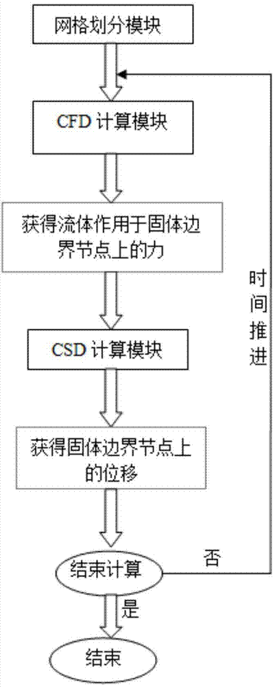
[0045] Embodiment 1: as Figure 1-3 As shown, a fluid-solid coupling calculation method based on fixed grid technology, the specific steps of the method are as follows:

[0046] Step1. Call the mesh division module and use two sets of grids: flow field area and solid area; the flow field area is discretized by Cartesian grid under the Euler description, and the solid area is described by Lagrangian using limited fit meta-grid discretization;

[0047] Step2. Call the flow field CFD (computational fluid dynamics) calculation module, and use the submerged boundary method based on the step-by-step projection to solve the flow control equation of the incompressible viscous Newtonian fluid, update the flow field state variables, and obtain the fluid acting on the solid boundary node at the same time force on

[0048] Step3. Call the solid CSD (computational solid dynamics) calculation module, use the finite element method, solve the solid dynamics control equation, update the soli...

Embodiment 2

[0079] Embodiment 2: as Figure 1-3 As shown, a fluid-solid coupling calculation method based on fixed grid technology, the specific steps of the method are as follows:

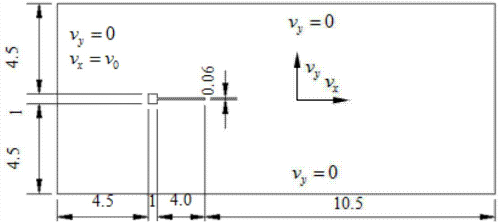
[0080] A stationary rigid square column is submerged in an incompressible flow field, the flow at the left inlet is assumed to be a uniform flow field, and the velocity is v x =v 0 ,v y =0. An elastic cantilever beam (solid density ρ s =100Kg / m 3 , elastic modulus E = 25Gpa, Poisson's ratio ν = 0.35). At rest, the beam axis is parallel to the far-field flow direction, and the inlet velocity v 0 =51.3cm / s, Reynolds number Re=ρ f Dv 0 / μ f =333, where D=1cm is the side length of the rigid square column, and the height of the flexible cantilever beam is 0.06D.

[0081] S1: Meshing

[0082] The flow field area (including fluid and solid areas) is divided into Cartesian grids under the Euler description. The grid is a uniform quadrilateral grid with a grid spacing of h=0.01D, and the unit coordinate inf...


PUM

PropertyMeasurementUnit
Elastic modulusaaaaaaaaaa

Abstract

The present invention relates to a fluid-solid coupling computing method based on a fixed grid technology and belongs to the technical field of fluid-solid coupling simulation. The method comprises the following steps of: A, calling a grid dividing module which adopts two sets of grids including an overall physical area formed by fluid and solid and a solid area; B, calling a fluid field computing CFD module to update a fluid field state variable and simultaneously obtain a force applied to a solid boundary node by the fluid; C, calling a solid computing CSD module to update a solid state variable and simultaneously obtain displacement and speed of the solid boundary node; D, calling a result output module to output the solid state variable and the fluid field information to a file for use in post-processing; and E, judging whether to end computing. According to the fluid-solid coupling computing method, a movable grid module is successfully avoided, so that the computing resources for updating the grid are greatly saved; and the defect that the action force on a fluid-solid interface is hard to calculate accurately because of traditional complex inner grid updating and boundary grid control computing on the basis of movable grid technology can be overcome.

Description

technical field [0001] The invention relates to a fluid-solid coupling calculation method based on fixed grid technology, and belongs to the technical field of fluid-solid coupling simulation. Background technique [0002] One of the difficulties in fluid-structure interaction problems is that fluids and solids use different mathematical description frameworks. Usually, the fluid motion is described by Euler, while the solid motion is described by Lagrange: the traditional fluid-solid coupling method, the grid of the fluid area is dynamically updated with the movement of the solid boundary, and the grid operation and grid quality control process is abnormal Complicated, the obtained velocity distribution near the boundary layer has a large error. For this reason, the present invention proposes a fluid-solid coupling calculation method based on fixed grid technology, which avoids the use of a dynamic grid calculation module, and has a simple calculation process and easy prog...

Claims


Application Information

Patent Timeline
IPC IPC(8): G06F17/50
Inventor 王文全闫妍
Owner KUNMING UNIV OF SCI & TECH
Why Eureka
Try Eureka