Transformer magnetic shunt structure

A magnetic shunt and transformer technology, applied in the field of power transformers, can solve the problems affecting the economy and reliability of the transformer, the high temperature rise of the hot spot at the end, and the overheating of the structural parts, so as to achieve practical reliability, reduce the temperature rise of the hot spot, reduce The effect of small loss

Inactive Publication Date: 2015-08-19
CHINA XD ELECTRIC CO LTD
View PDF4 Cites 1 Cited by
  • Summary
  • Abstract
  • Description
  • Claims
  • Application Information

AI Technical Summary

Problems solved by technology

Magnetic flux leakage will generate eddy current loss in the winding, especially at the end. At the same time, eddy current loss will also be generated when the magnetic flux leakage passes through the structural parts, which will cause problems such as excessive temperature rise of hot spots at the end of the winding and overheating of structural parts.
These unfavorable factors seriously affect the economy and reliability of transformer operation

Method used


Image

  • Transformer magnetic shunt structure
  • Transformer magnetic shunt structure
  • Transformer magnetic shunt structure

Examples


Embodiment Construction

[0023] The present invention will be further described in detail below in conjunction with the accompanying drawings, which are explanations rather than limitations of the present invention.

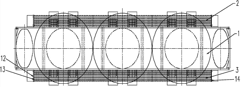
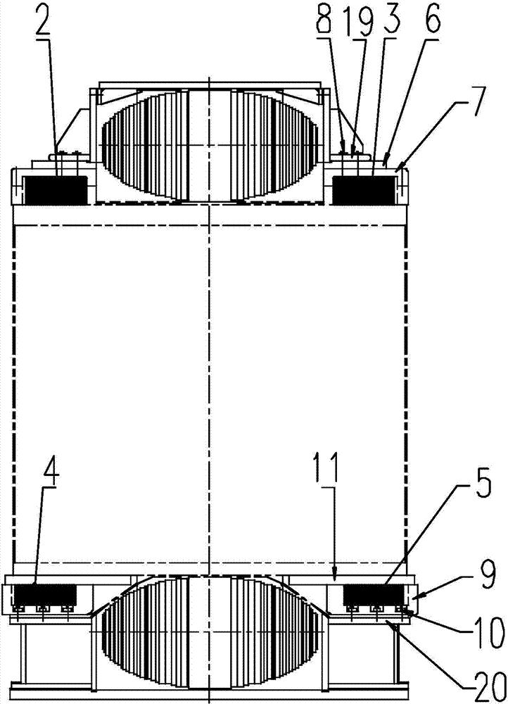
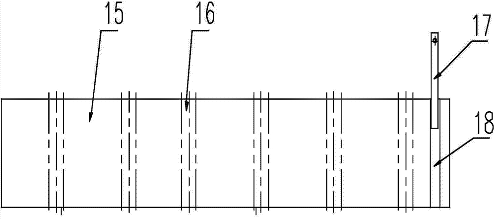
[0024] Such as Figures 1 to 3 As shown, the magnetic shunt structure of a transformer in the present invention includes an upper magnetic shunt installed above the pressure plate of the transformer 1 and a lower magnetic shunt installed under the supporting plate of the transformer 1 .

[0025] Wherein, the upper magnetic shunt includes a first upper magnetic shunt 2 and a second upper magnetic shunt 3 arranged on both sides of the upper iron yoke, and both the first upper magnetic shunt 2 and the second upper magnetic shunt 3 pass through the first upper magnetic shunt 2 and the second upper magnetic shunt 3 A fastening device is installed above the pressure plate of the transformer 1 . The first fastening device includes a first wooden part 7, a first adjusting cardboard 6 and an upp...


PUM


Abstract

The invention discloses a transformer magnetic shunt structure which comprises an upper magnetic shunt mounted above a transformer pressing plate and a lower magnetic shunt mounted below the same. By the transformer magnetic shunt structure, distribution of a leakage magnetic field can be changed, hot-point temperature rise of a transformer winding can be lowered effectively, overheating of structural members can be prevented, and loss of transformer can be reduced. In addition, the transformer magnetic shunt structure is practical, reliable, low in manufacturing cost, convenient to mount and suitable for transformers different in voltage class and capacity.

Description

Technical field: [0001] The invention belongs to the technical field of power transformers, and in particular relates to a transformer magnetic shunt structure. Background technique: [0002] During the operation of the transformer, in addition to the main magnetic flux circulating in the iron core, there is always a leakage magnetic flux outside the iron core. With the improvement of the capacity of a single transformer and the popularization and use of high-impedance transformers, the leakage flux of the transformer has increased a lot. Magnetic flux leakage will generate eddy current loss in the winding, especially at the end. At the same time, eddy current loss will also be generated when the magnetic flux leakage passes through the structural parts, which will lead to problems such as excessive temperature rise of hot spots at the end of the winding and overheating of structural parts. These unfavorable factors seriously affect the economy and reliability of transforme...

Claims


Application Information

Patent Timeline
Patent Type & Authority Applications(China)
IPC IPC(8): H01F27/24H01F3/12
Inventor 李子兴瞿建锋张逸孙佳忠刘智浩
Owner CHINA XD ELECTRIC CO LTD
Why Eureka
Try Eureka