Seamless metal frame antenna structure
A metal frame and antenna structure technology, applied in the structural form of radiating elements, antenna supports/mounting devices, etc., can solve problems such as large gap spacing, complex radiator wiring design, and incompatible with the development trend of miniaturization of electronic products. Achieve the effect of small space occupation and simple structure design
- Summary
- Abstract
- Description
- Claims
- Application Information
AI Technical Summary
Problems solved by technology
Method used
Image

Examples
Embodiment 1
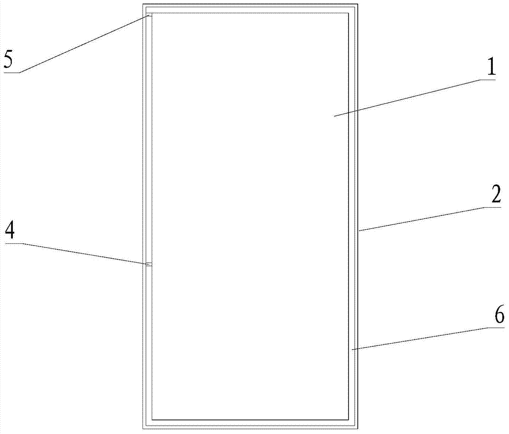
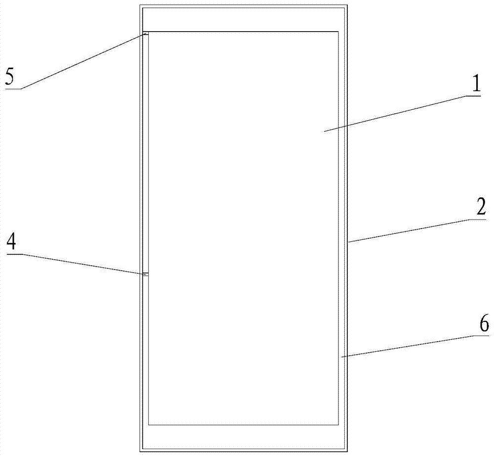
[0039] Please refer to figure 2 , a seamless metal frame antenna structure, including a seamless metal frame 2, an antenna feed point 4 and an antenna matching point 5; the seamless metal frame 2 is a complete metal shell without a slit, and a The metal device 1 is completely enclosed, and a square ring gap 6 is formed between the seamless metal frame 2 and the metal device 1; the metal device 1 can include motherboards, screens, batteries and other components, which can be regarded as a square metal block; the antenna feed point 4 and the antenna matching point 5 are arranged in the square ring slot 6, and the antenna matching point 5 includes a variable capacitance.
[0040] The seamless metal frame antenna structure also includes four metal shorting blocks 3, the four metal shorting blocks 3 are set in the square ring slit 6, two of which are set in a pair of square ring slits 6 On the corner, the other two are arranged on the side of the square ring slit, and the square ...
Embodiment 2
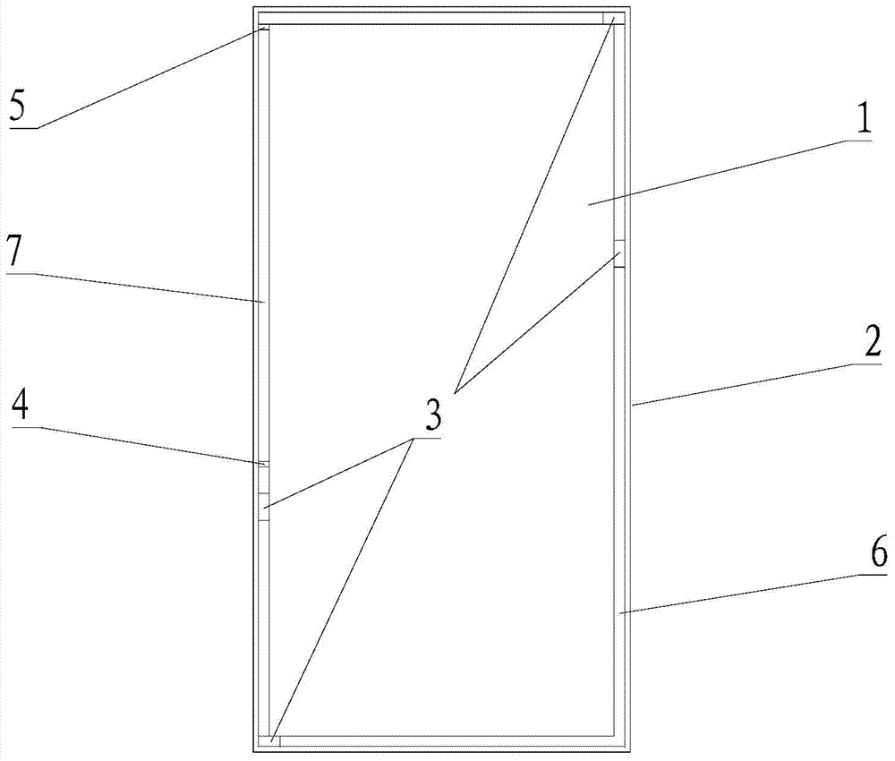
[0043] Please refer to image 3 The difference between this embodiment and the first embodiment is that the distance between the top edge of the metal device 1 and the metal frame 2 is greater than the distance between the side edges of the metal device 1 and the metal frame 2 . Due to the broadband and multi-frequency characteristics of the LTE antenna, the antenna feed point 4 is set by using the narrow slot on the side of the square ring slot 6, and the antenna matching point 5 is set by the wide slot on the top side, which can effectively widen the low-frequency bandwidth of the antenna.
[0044] The distance between the top edge of the metal device 1 and the metal frame 2 can be more than 7 mm, preferably more than 8 mm; the distance between the side of the metal device 1 and the metal frame 2 can be more than 1.5 mm, preferably more than 2 mm .
Embodiment 3
[0046] Please refer to Figure 4 with Figure 5 , this embodiment is a combination of Embodiment 1 and Embodiment 2. The seamless metal frame antenna structure includes four metal shorting blocks 3, which divide the square ring gap 6 between the metal device 1 and the seamless metal frame 2 into four part; at the same time, the distance between the top edge and the bottom edge of the metal device 1 and the metal frame 2 is greater than the distance between the side edges of the metal device 1 and the metal frame 2 .
[0047] Such as Image 6 Shown is the antenna return loss curve diagram obtained by simulating and optimizing the design of the antenna feed point 4 and the antenna matching point 5 in Embodiment 3 of the present invention, where the abscissa is the frequency, and the ordinate is the return loss. It can be seen that the structure of the antenna It can cover the LTE high-frequency band, but the low-frequency bandwidth is narrow and cannot be covered. At this time...
PUM
 Abstract
Description
Claims
Application Information
 - R&D
- Intellectual Property
- Life Sciences
- Materials
- Tech Scout
- Unparalleled Data Quality
- Higher Quality Content
- 60% Fewer Hallucinations
Browse by: Latest US Patents, China's latest patents, Technical Efficacy Thesaurus, Application Domain, Technology Topic, Popular Technical Reports.
© 2025 PatSnap. All rights reserved.Legal|Privacy policy|Modern Slavery Act Transparency Statement|Sitemap|About US| Contact US: help@patsnap.com