Series machine water-cooling structure

A technology of series excitation motor and cooling structure, which is applied in the direction of electrical components, electromechanical devices, electric components, etc., can solve the problems of poor cooling effect, inability to commutate, cooling, etc., to achieve good cooling effect, overcome large wind consumption, flow smooth effect

Active Publication Date: 2015-08-19
BOSUN TOOLS CO LTD
View PDF5 Cites 6 Cited by
  • Summary
  • Abstract
  • Description
  • Claims
  • Application Information

AI Technical Summary

Problems solved by technology

[0003] First, the large wind consumption
[0004] Second, the heat on the surface of the rotor can only be taken away by the wind flow, and the cooling effect is poor
However, it takes a certain amount of time for the cooling water to pass through the entire spiral channel, so the cooling effect is not ideal
And this simple spiral water channel is not suitable for series motors, because there are commutators and brushes on the top of series motors. Due to the existence of brushes, the cooling water pipe cannot be spirally coiled outside the steering gear, so it cannot be used for commutation. Inverter cooling, thereby affecting the cooling effect of the entire motor
It is precisely because of the lack of effective cooling methods that the power of the existing series motors is generally not large

Method used


Image

  • Series machine water-cooling structure
  • Series machine water-cooling structure
  • Series machine water-cooling structure

Examples


Embodiment 1

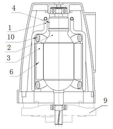
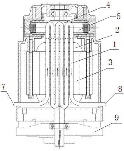
[0031] A water-cooled structure of a series motor, such as figure 1 with figure 2 As shown, the cooling pipe 1 has a circular structure from the position of the stator 3 to the position of the commutator 4, that is, the water inlet 7 of the cooling pipe 1 is set on one side of the lower end of the casing, and the cooling pipe 1 starts from the water inlet end and runs from the stator 3 The bottom is bent inward along the vertical direction of the outer surface of the stator 3, close to the lower edge of the commutator 4 from the outer surface of the stator to the top of the rotor 2, and the depth direction reaches the outer surface of the commutator 4 but does not touch the commutator. the outer surface of the commutator 4, and then go up along the vertical direction of the commutator 4 to reach the upper edge of the commutator 4, and then turn back to the bottom of the stator 3 in the same way to form a back-shaped unit, repeating this for several times After the back-shape...

Embodiment 2

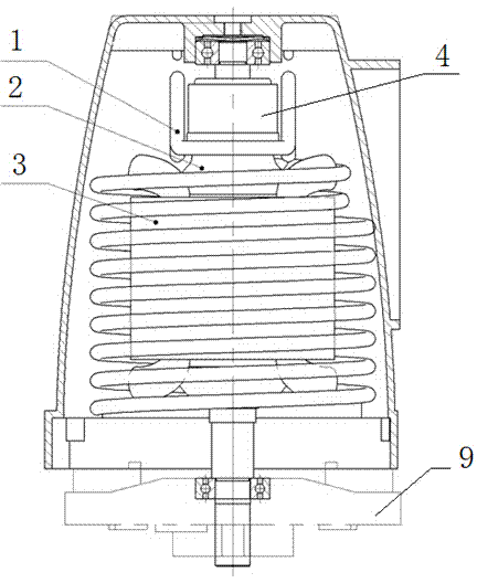
[0033] A water-cooled structure of a series motor, such as image 3 with Figure 4 As shown, the cooling pipe 1 is arranged in a spiral structure at the stator 3, and is designed as a loop structure at the two sides of the commutator position 4 parallel to the brush 5, that is, the water outlet 8 of the cooling pipe 1 is arranged in the casing On one side of the lower end, the cooling pipe 1 starts from the water inlet end and spirally coils on the outer surface of the stator 3 along the vertical direction of the outer surface of the stator 3 from the bottom of the stator 3 and close to the outer surface of the stator 3 to the lower edge of the commutator 4 Bend inward after the position, the depth direction reaches the outer surface of the commutator 4 but does not connect with the outer surface, and then goes up along the vertical direction of the commutator 4 to the upper edge of the commutator 4 and then uses the same way back to the lower edge of the commutator 4 to form...


PUM


Abstract

The invention discloses a series motor water-cooling structure comprising a motor rotor, a stator, a commutator, and a cooling pipe. The cooing pipe is mainly composed of two mutually-communicated parts, namely, a part near the outer surface of the commutator and a part adhered to the outer surface of the stator. A water inlet and a water outlet of the cooling pipe are respectively disposed at the two sides of a motor shell. By adopting the device, the size of a fan is reduced, the air volume is reduced, the defect of motor air-cooling is overcome, a series motor can be cooled effectively, and a high-power series motor is made possible.

Description

technical field [0001] The invention relates to the technical field of motor cooling, in particular to a water cooling structure of a series motor. Background technique [0002] At present, the cooling structure of the motor is mainly an air-cooled structure, that is, a fan is installed at the front end of the rotor, and the fan rotates to generate airflow, which enters the motor through the air inlet on the casing, and the airflow passes through the air gap between the stator and the rotor, and then flows from the The air outlet at the lower end of the casing flows out and takes away the heat, thereby cooling the rotor with wind. The disadvantages of this structure are: [0003] First, the wind consumption is relatively large. [0004] Second, the heat on the surface of the rotor can only be taken away by the wind flow, and the cooling effect is poor. [0005] Third, the motor noise is louder, the bigger the fan, the bigger the air flow, and the better the cooling effect...

Claims


Application Information

Patent Timeline
Patent Type & Authority Applications(China)
IPC IPC(8): H02K9/19H02K9/06
CPCH02K9/06H02K9/197H02K9/28
Inventor 田建春翟永红崔学彬
Owner BOSUN TOOLS CO LTD
Why Eureka
Try Eureka