Cascaded multi-level power electronic transformer based on DSP (Digital Signal Processor)/FPGA (Field Programmable Gate Array) cooperative control

A collaborative control and power electronics technology, applied to electrical components, output power conversion devices, and AC networks to reduce harmonics/ripples, etc., can solve problems such as difficult timing synchronization and reduced algorithm efficiency, reaching the number of IO ports Flexible configuration, fast calculation speed, and improved efficiency

Inactive Publication Date: 2015-08-19
GUANGXI UNIV
View PDF2 Cites 17 Cited by
  • Summary
  • Abstract
  • Description
  • Claims
  • Application Information

AI Technical Summary

Problems solved by technology

If a single DSP controller is used, the control algorithms of each control system will compete and couple with the computing resources and timing of the DSP, resulting in reduced algorithm efficiency
However, if multiple DSP controllers are used, timing synchronization among the controllers is difficult to achieve

Method used


Image

  • Cascaded multi-level power electronic transformer based on DSP (Digital Signal Processor)/FPGA (Field Programmable Gate Array) cooperative control
  • Cascaded multi-level power electronic transformer based on DSP (Digital Signal Processor)/FPGA (Field Programmable Gate Array) cooperative control
  • Cascaded multi-level power electronic transformer based on DSP (Digital Signal Processor)/FPGA (Field Programmable Gate Array) cooperative control

Examples


Embodiment Construction

[0036] The embodiments of the present invention will be described in further detail below in conjunction with the accompanying drawings, but this does not constitute a limitation to the protection scope of the present invention.

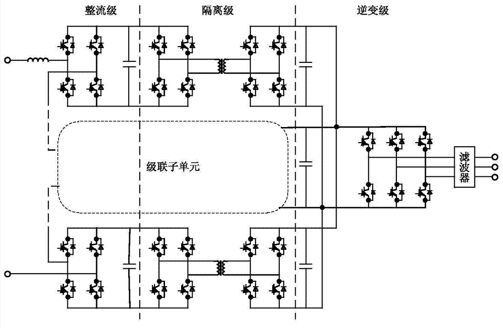
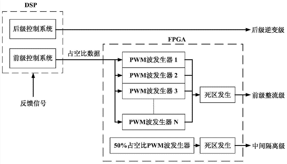
[0037] Such as figure 1 As shown, the cascaded multi-level power electronic transformer based on DSP / FPGA cooperative control includes a front-stage rectification stage circuit, an intermediate isolation stage circuit, a rear-stage inverter stage circuit and a control module;

[0038] The power frequency alternating current is rectified by the pre-stage rectification stage circuit to become the first direct current input to the intermediate isolation stage circuit; the intermediate isolation stage circuit first modulates the first direct current into a high frequency square wave alternating current, and then converts the high frequency square wave alternating current through a high frequency transformer Voltage level transformation and isolation proc...


PUM


Abstract

The invention discloses a cascaded multi-level power electronic transformer based on DSP (Digital Signal Processor) / FPGA (Field Programmable Gate Array) cooperative control, comprising a pre-stage rectification-level circuit, a middle isolation-level circuit, a rear-stage inversion-level circuit and a cooperative control module. Power frequency alternating current is rectified to generate first direct current via the pre-stage rectification-level circuit, the first direct current is modulated via the middle isolation-level circuit to generate high frequency square wave alternating current, the high frequency square wave alternating current is subjected to voltage grade conversion, isolation and demodulation via a high-frequency transformer to generate second direct current, and the second direct current is inverted via the rear-stage inversion-level circuit to output required alternating current. The cooperative module comprises a DSP module and an FPGA module and is used for controlling PWM (Pulse-Width Modulation) waves of the pre-stage rectification-level circuit, the middle isolation-level circuit and the rear-stage inversion-level circuit respectively. The cascaded multi-level power electronic transformer provided by the invention provides enough PWM ports to achieve circuit integration, achieves bidirectional energy flow, reactive compensation, quality control of electric energy and access of renewable energy source and energy storage equipment, is suitable for high-voltage and large-power places, can reduce output harmonic waves without improving the switching frequency, reduces loss and is free of voltage-sharing problems.

Description

technical field [0001] The invention belongs to the technical field of power electronic transformers, in particular to a cascaded multilevel power electronic transformer based on DSP / FPGA cooperative control. Background technique [0002] Power electronic transformer (PET), also known as solid-state transformer (SST), or intelligent universal transformer (IUT), is a kind of function that integrates voltage conversion, frequency conversion, dynamic reactive power compensation, power quality control and uninterruptible power supply. intelligent power distribution equipment. With the development of power electronics technology, the research on power electronic transformers has also developed from low-voltage and low-power to high-voltage and high-power, but the technology of high-voltage power devices has become one of the main factors restricting the development of power electronic transformers to high-voltage and high-power, such as high-voltage The voltage level of silicon ...

Claims


Application Information

Patent Timeline
IPC IPC(8): H02M5/458H02M7/797H02J3/18H02J3/01
CPCY02E40/30Y02E40/40
Inventor 卢子广李捷杨达亮李卓田向渝赵刚
Owner GUANGXI UNIV
Why Eureka
Try Eureka