Check patentability & draft patents in minutes with Patsnap Eureka AI!

Simple frequency multiplier based on pulse amplification trigger circuit

A technology of trigger circuit and pulse amplification, which is applied in the electronic field, can solve problems such as wrong trigger signals and frequency multiplier signal instability, and achieve the effects of avoiding wrong trigger signals, stable signals, and low cost

Inactive Publication Date: 2015-08-19
CHENGDU CHUANGTU TECH
View PDF4 Cites 0 Cited by
  • Summary
  • Abstract
  • Description
  • Claims
  • Application Information

AI Technical Summary

Problems solved by technology

[0003] The purpose of the present invention is to overcome the defect that the traditional frequency multiplier is easy to generate a wrong trigger signal and make the signal output by the frequency multiplier unstable, and to provide a simple frequency multiplier based on a pulse amplification trigger circuit

Method used


Image

  • Simple frequency multiplier based on pulse amplification trigger circuit

Examples


Embodiment

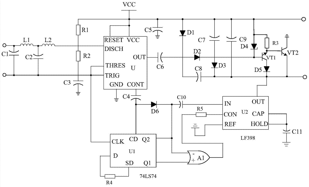
[0018] Such as figure 1 As shown, the present invention includes a buffer circuit, a voltage-controlled oscillating circuit connected with the buffer circuit, a microwave circuit connected with the voltage-controlled oscillating circuit, and a control circuit connected with the microwave circuit. A pulse trigger circuit is connected in series between the controlled oscillation circuit and the control circuit.

[0019] Wherein, the pulse trigger circuit is the focus of the present invention, which is composed of an amplifier chip U1, a NOR gate A1, a trigger chip U2, a resistor R4, a resistor R5, a polar capacitor C10, a polar capacitor C11 and a diode D6. When connected, the resistor R4 is connected in series between the D pin and the SD pin of the amplifier chip U1, the P pole of the diode D6 is connected to the CD pin of the amplifier chip U1, and its N pole is connected to the The IN pin of the trigger chip U2 is connected, one end of the resistor R5 is connected to the ou...


PUM


Abstract

The invention discloses a simple frequency doubler. The simple frequency doubler is characterized by being composed of a buffering circuit, a voltage-controlled oscillation circuit connected with the buffering circuit, a microwave circuit connected with the voltage-controlled oscillation circuit, and a control circuit connected with the microwave circuit; the voltage-controlled oscillation circuit is composed of an oscillation chip U, a capacitor C3, a capacitor C5, a capacitor C6 and the like, wherein the positive electrode of the capacitor C3 passes a resistor R2 and a resistor R1 and then is connected with a VCC pin of the oscillation chip U, the negative electrode of the capacitor C3 is grounded, the positive electrode of the capacitor C5 is connected with the VCC pin of the oscillation chip U, the negative electrode of the capacitor C5 is grounded, the positive electrode of the capacitor C6 is connected with an OUT pin of the oscillation chip U, and the negative electrode of the capacitor C6 is connected with the microwave circuit. The simple frequency doubler is simple in overall structure, easy to operate, low in manufacturing cost and capable of saving a large amount of manufacturing cost.

Description

technical field [0001] The invention relates to the field of electronics, in particular to a simple frequency multiplier based on a pulse amplification trigger circuit. Background technique [0002] A frequency multiplier is a circuit that makes the output signal frequency equal to an integer multiple of the input signal frequency. With the continuous development of electronic technology, frequency multipliers are used more and more widely. For example, the transmitter can make the main oscillator oscillate at a lower frequency to improve frequency stability; Large frequency offset; in the phase keying communication machine, the frequency multiplier is an important component of the carrier recovery circuit. However, the currently used frequency multiplier is prone to generate false trigger signals during work, which makes the output signal of the frequency multiplier unstable and cannot meet people's needs. Contents of the invention [0003] The purpose of the present in...

Claims


Application Information

Patent Timeline
Patent Type & Authority Applications(China)
IPC IPC(8): H03B19/00
Inventor 周云扬
Owner CHENGDU CHUANGTU TECH
Features
  • R&D
  • Intellectual Property
  • Life Sciences
  • Materials
  • Tech Scout
  • Unparalleled Data Quality
  • Higher Quality Content
  • 60% Fewer Hallucinations
Learn More