Technology and system for treating hydrochloric acid regeneration device tail gas

A regeneration device and exhaust gas treatment technology, applied in the separation of dispersed particles, chemical instruments and methods, separation methods, etc., can solve the problems of high residents' opinions, environmental hazards, equipment and building corrosion, etc., and achieve quick results, reduce load, and invest. less effect

Inactive Publication Date: 2015-08-26
鞍山创鑫环保科技股份有限公司
View PDF3 Cites 8 Cited by
  • Summary
  • Abstract
  • Description
  • Claims
  • Application Information

AI Technical Summary

Problems solved by technology

[0002] At present, the tail gas treatment process of the hydrochloric acid regeneration unit commonly used is: the high-temperature furnace gas of about 395°C discharged from the roasting furnace of the hydrochloric acid regeneration unit is sprayed with waste acid in the pre-concentrator to cool down to about 97°C, and then enters the absorption tower and the washing tower Reverse contact with the upper spray water to absorb and wash the acid gas. At this time, the acid-containing furnace gas has been saturated with water and turned into water vapor, which is discharged into the atmosphere from the chimney of the device. After the discharged acid-containing water vapor condenses into water and falls, it will affect the plant area The nearby equipment and buildings cause certain corrosion, causing harm to the environment, especially the residents around the factory area have great opinions

Method used


Image

  • Technology and system for treating hydrochloric acid regeneration device tail gas

Examples


Embodiment Construction

[0022] The specific embodiment of the present invention will be further described below in conjunction with accompanying drawing:

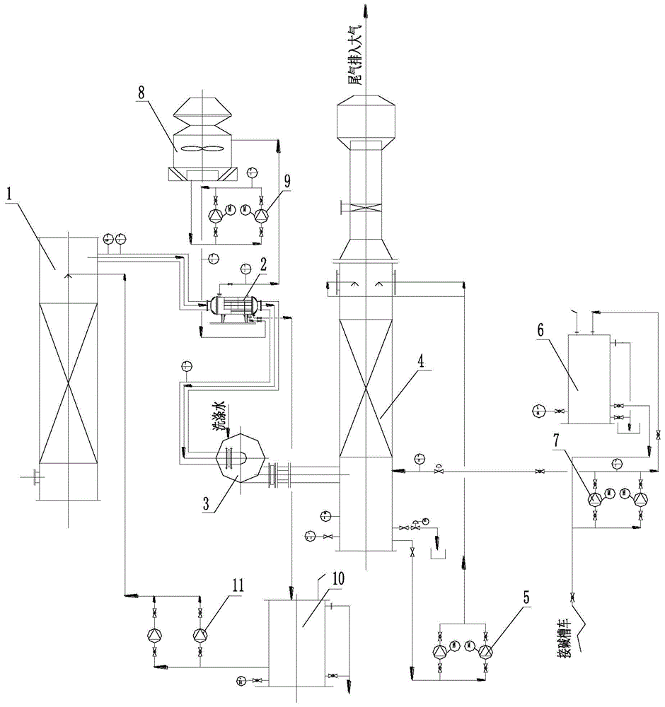
[0023] See figure 1 , is a process flow diagram of the present invention, a kind of hydrochloric acid regeneration device tail gas treatment process of the present invention, comprises the steps:

[0024] 1) The tail gas from the hydrochloric acid regeneration unit coming out of the absorption tower 1 enters the condenser 2 to exchange heat indirectly with the cooling water, condenses the tail gas above 90°C to below 40°C, and the condensate after part of the water vapor in the tail gas condenses enters the collection water Tank 10 is used as the spray liquid of absorption tower 1;

[0025] 2) The cooling water inlet temperature is 30-32°C, after heat exchange, the temperature rises to 35-37°C, then goes to the cooling tower 1, re-cools to 30-32°C, and then returns to the condenser 2 for recycling, during which the evaporated water is regularly r...


PUM


Abstract

The invention relates to a technology and a system for treating hydrochloric acid regeneration device tail gas. The technology comprises steps as follows: 1) the hydrochloric acid regeneration device tail gas coming out of an absorption tower enters a condenser to indirectly exchange heat with cooling water, and condensate formed after condensation of part of water vapor in the tail gas enters a collecting water tank to be used as a spraying liquid of the absorption tower; 2) the cooling water is heated through heat exchange, then enters a cooling tower and returns to the condenser for recycling after cooled again; 3) the tail gas comes out of the condenser, is pressurized by a smoke exhaust fan and enters an alkaline washing tower, hydrochloric acid in the alkaline washing tower is thoroughly neutralized, and the acid content of the finally discharged tail gas is smaller than or equal to 10 mg / m<3>. With the adoption of the technology and the system, up-to-standard discharge of the hydrochloric acid regeneration device tail gas is realized, meanwhile, the process cooling water can be recycled, the condensate is used as the spraying liquid of the absorption tower, so that water for washing is saved, and power consumption is reduced; the total discharge amount of the tail gas can be reduced, the load of the smoke exhaust fan is reduced, and the technology is simple and easy to implement, low in investment and particularly applicable to transformation of old plants, takes effect quickly and is another good method worthy of popularization for energy conservation and emission reduction.

Description

technical field [0001] The invention relates to the technical field of energy saving and emission reduction of a hydrochloric acid regeneration device in the metallurgical industry, in particular to a tail gas treatment process and a treatment system of a hydrochloric acid regeneration device. Background technique [0002] At present, the tail gas treatment process of the hydrochloric acid regeneration unit commonly used is: the high-temperature furnace gas of about 395°C discharged from the roasting furnace of the hydrochloric acid regeneration unit is sprayed with waste acid in the pre-concentrator to cool down to about 97°C, and then enters the absorption tower and the washing tower Reverse contact with the upper spray water to absorb and wash the acid gas. At this time, the acid-containing furnace gas has been saturated with water and turned into water vapor, which is discharged into the atmosphere from the chimney of the device. After the discharged acid-containing water...

Claims


Application Information

Patent Timeline
Patent Type & Authority Applications(China)
IPC IPC(8): B01D53/78
Inventor 孟祥全孟剑张嘉鹏洪成峰樊江波刘伟
Owner 鞍山创鑫环保科技股份有限公司
Why Eureka
Try Eureka