Ducted power device and aircraft

A power plant and duct technology, applied in the field of aircraft, can solve problems such as disturbance, low aerodynamic efficiency, and the inability of gas to flow into the duct evenly

Active Publication Date: 2015-08-26
ZHUHAI PANLEI INTELLIGENT TECH CO LTD
View PDF9 Cites 3 Cited by
  • Summary
  • Abstract
  • Description
  • Claims
  • Application Information

AI Technical Summary

Problems solved by technology

Because the gas outside the duct is not an ideal gas, there are disturbances and uncertain flow directions, and the gas cannot flow uniformly into the duct
Especially in the airflow environment with complex environment, the turbulence at the entrance of the duct is more serious, so the aerodynamic efficiency is low

Method used


Image

  • Ducted power device and aircraft
  • Ducted power device and aircraft
  • Ducted power device and aircraft

Examples


Embodiment Construction

[0023] The present invention will be further described below in conjunction with the accompanying drawings and embodiments.

[0024] The first embodiment of the ducted power device

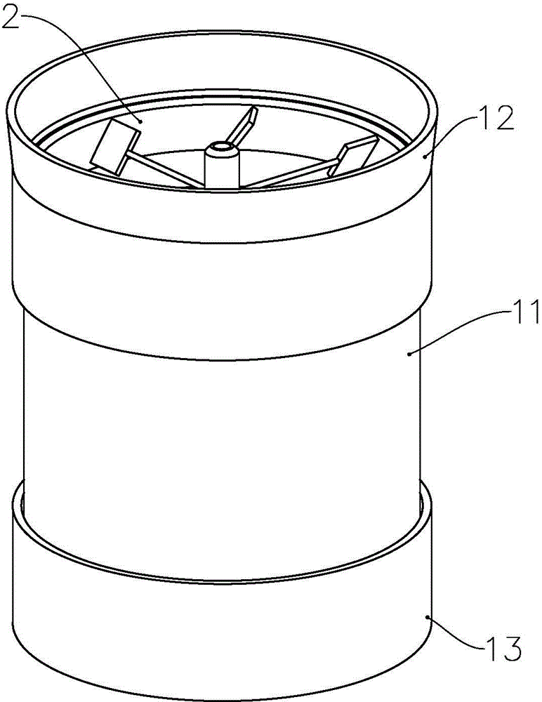
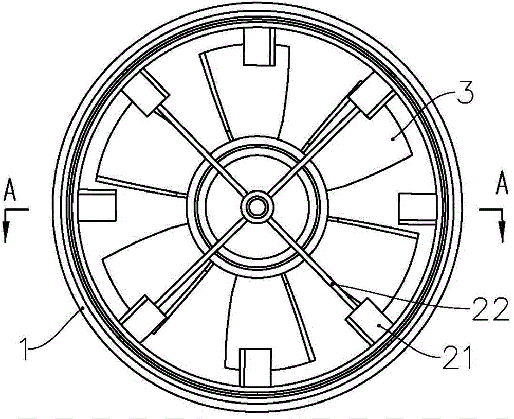
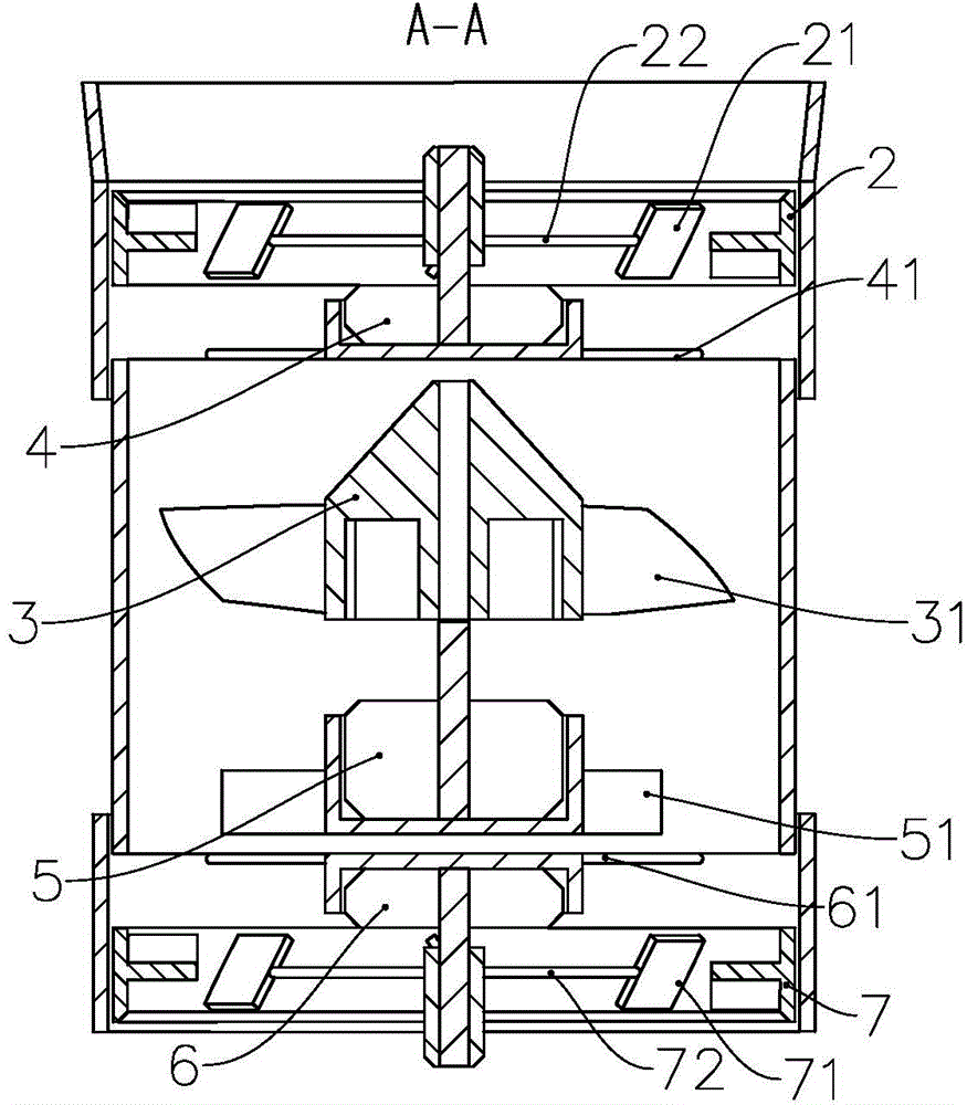
[0025] see Figure 1 to Figure 3 , the present embodiment includes a duct 1 with a circumferential wall, the duct 1 includes a lip 12 at the air inlet end, a main body portion 11 in which the rotor 3 is installed, and a tail portion 13 at the air outlet end. Wherein the outer diameter of the lip 12 and the tail 13 is greater than the outer diameter of the main body 11, the lip 12 is provided with a rotating sleeve 2 (the first rotating sleeve) that can rotate relative to the lip 12, and the inner wall of the lip 12 is in contact with the rotating sleeve. There may be a certain gap between the outer walls of the sleeve 2, but preferably the gap is small to prevent air flow from entering the duct from the gap, and in addition, the small gap also makes the ducted power device more compact. The inne...


PUM


Abstract

The invention provides a ducted power device and an aircraft. The ducted power device comprises guide plates which are configured to allow the direction of the component velocity of air flow, guided by the guide plates to move along the duct direction, to be opposite to the rotary direction of rotors, so that relative velocity between the air flow and the rotors is increased, and not only can disturbed flow in the inlet of a duct be relieved, but also pneumatic efficiency of the ducted power device can be improved.

Description

technical field [0001] The invention relates to the field of aircraft, in particular, to a ducted power device and an aircraft with such a ducted power device. Background technique [0002] The ducted power unit is a kind of propulsion device with ducts arranged on the periphery of the rotor, and is widely used in various vehicles, especially aircrafts. Because the rotor blade tip is limited by the duct, the noise is small, the induced resistance is reduced, and the efficiency is high. At the same time, due to the encircling effect of the duct, the power unit has a compact structure, low aerodynamic noise, and good safety in use. [0003] When the ducted power plant is working, the rotation of the rotor drives the air into the duct from the entrance of the duct, also known as the lip, and the suction flow of the rotating blades generates a flow around the entrance of the duct to form a low-pressure area, causing the duct to generate additional tension. . Because the gas o...

Claims


Application Information

Patent Timeline
Patent Type & Authority Applications(China)
IPC IPC(8): B64C11/00
Inventor 何春旺
Owner ZHUHAI PANLEI INTELLIGENT TECH CO LTD
Why Eureka
Try Eureka