Flag textile cutting special tool and cutting method
A special tool and cutting method technology, which is applied in the field of flag textile cutting tools and flag textile cutting, can solve the problems of low processing accuracy, high reject rate, and excessively large flag cutting, and achieve high positioning accuracy and high production efficiency. The effect of improving efficiency and reducing scrap rate
- Summary
- Abstract
- Description
- Claims
- Application Information
AI Technical Summary
Problems solved by technology
Method used
Image
Examples
Embodiment 1
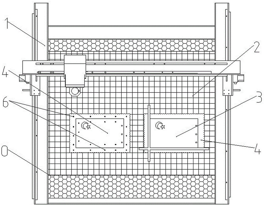
[0023] Such as figure 1 It can be seen that the special tool for cutting flag textiles in this embodiment includes a numerical control cutting machine 1 , and a grid plate 2 with scale lines is fixed on the table top of the numerical control cutting machine 1 .
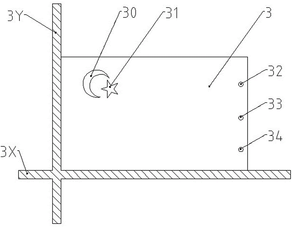
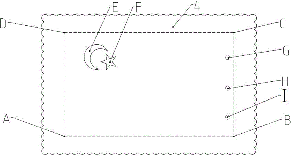
[0024] Such as figure 2 It can be seen that the banner template 3 is made according to the actual size of the target product, and is engraved with a first pattern mark pattern 30, a second pattern mark pattern 31, a third pattern mark pattern 32, a fourth pattern mark pattern 33, and a fifth pattern mark pattern. Pattern 34, the boundary of the first pattern mark pattern 30 is determined according to the boundary of the meniscus pattern E; the boundary of the second pattern mark pattern 31 is determined according to some vertices of the star pattern F; the third pattern mark pattern 32, the fourth pattern mark pattern 33. The boundaries of the fifth pattern marking pattern 34 are respectively determined according to...
Embodiment 2
[0037] On the basis of the first embodiment, this embodiment further optimizes the flag positioning method in step 3.
[0038] This embodiment also includes a backing plate 5 whose size matches the flag gray cloth 4 . Specific steps include:
[0039] (1) According to the proportion requirements of the product, draw the CAD graphics of the target flag.
[0040] (2) Fix the grid plate 2 on the table panel of the CNC cutting machine 1, and the latitude and longitude lines of the grid plate 2 are respectively set parallel to the X axis and the Y axis of the CNC cutting machine 1.
[0041] (3) if Figure 4 It can be seen that the flag gray cloth 4 printed with a pattern is fixed on the backing plate 5, and the fixed point is based on non-interference processing operations. In this embodiment, a plurality of thumbtacks 6 are used for fixing. Then the flag template 3 is placed on the flag gray cloth 4, so that the pattern printed on the flag gray cloth 4 is aligned with the patte...
PUM
 Abstract
Description
Claims
Application Information
 - R&D
- Intellectual Property
- Life Sciences
- Materials
- Tech Scout
- Unparalleled Data Quality
- Higher Quality Content
- 60% Fewer Hallucinations
Browse by: Latest US Patents, China's latest patents, Technical Efficacy Thesaurus, Application Domain, Technology Topic, Popular Technical Reports.
© 2025 PatSnap. All rights reserved.Legal|Privacy policy|Modern Slavery Act Transparency Statement|Sitemap|About US| Contact US: help@patsnap.com


